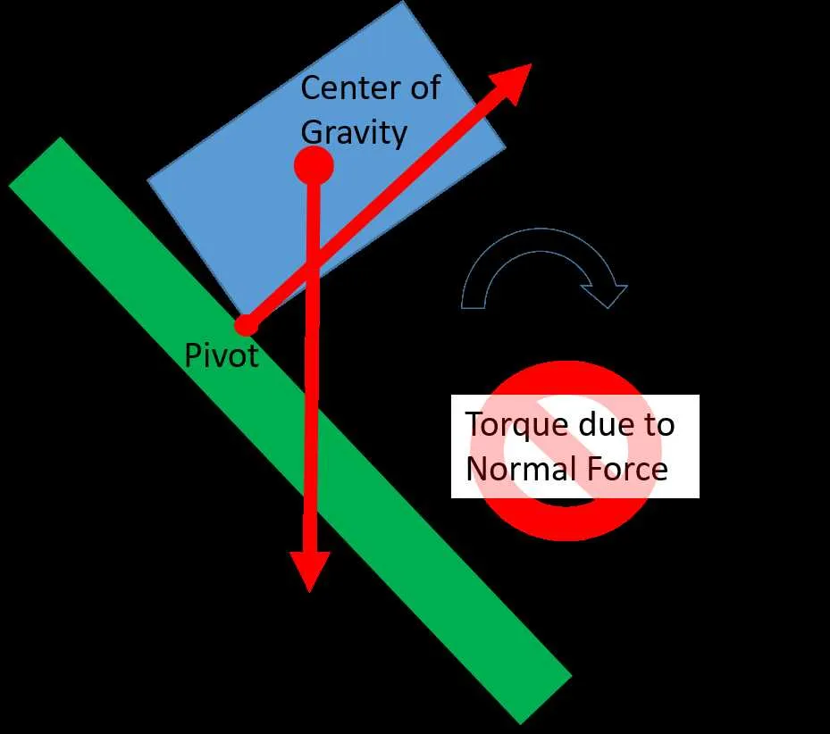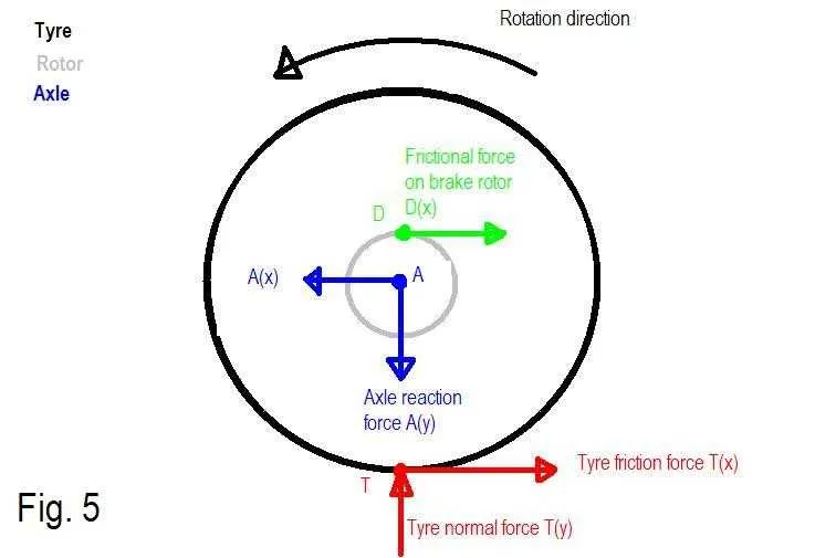
When analyzing mechanical systems, one of the most effective ways to understand rotational forces is by constructing a clear representation of the forces acting on an object and their impact on rotation. Start by isolating the object of interest and representing all external forces and the corresponding moments in a well-organized manner. Ensure that each force is labeled correctly, and moments are calculated based on the perpendicular distance from the pivot point to the line of action of the force.
Identify the axis of rotation first, as it serves as the reference for all calculations. The position and direction of applied forces will determine the magnitude and direction of the resulting moments. In static systems, the sum of all moments around the axis must equal zero, ensuring equilibrium. This principle is essential for solving for unknown forces or moments.
Next, it is crucial to consider the vector nature of the moments. Each rotational force has a specific direction, either clockwise or counterclockwise. Indicating these directions will help in establishing the correct equilibrium conditions. For more complex systems, apply the principles of moment arms and leveraging distances to calculate the moment’s effect on the system’s balance.
By using accurate force placement and proper calculation techniques, this approach allows you to solve for the unknowns and ensure that the mechanical system is stable under the applied loads. Precision in moment representation leads to more accurate predictions of an object’s behavior in various mechanical contexts.
Analyzing Rotational Forces and Moments
To analyze rotational effects on an object, start by identifying all the forces acting on it. Focus on the point of rotation and draw vectors representing these influences. Each force generates a moment that can be calculated as the force multiplied by the perpendicular distance from the pivot point. Ensure that you account for both the magnitude and the direction of these forces, as they can either promote or resist rotation.
Determine the net rotational effect by adding all moments together, considering the direction of rotation each one produces. A positive moment usually induces counterclockwise motion, while a negative moment leads to clockwise rotation. Ensure that you resolve forces into their components and correctly assign them to the appropriate distances to avoid miscalculations.
For accuracy, take into account the object’s dimensions and the placement of the forces in relation to the axis of rotation. Additionally, use appropriate units for each component (e.g., Newton-meters for moments) and verify that all angles are correctly measured from the axis of interest. Using a systematic approach will ensure correct results in rotational analysis.
How to Represent Rotational Force in a System
To show the effect of rotational force, follow these steps:
- Identify the pivot point: Mark the location where the object rotates or is supported. This point is crucial for understanding the direction of the turning force.
- Determine the direction: Indicate whether the force causes clockwise or counterclockwise rotation. Use arrows to clearly represent this.
- Locate the line of action: Draw a line representing the line along which the force is applied. This will help to understand how far from the pivot the force is acting.
- Calculate the moment arm: Measure the perpendicular distance from the pivot point to the line of action of the force. This distance is vital for computing the strength of the turning effect.
- Include force magnitude: Specify the size of the applied force using labels or annotations. This gives clarity on the magnitude that is contributing to rotation.
For clarity, combine these elements into a single visual representation. Be sure the pivot, force direction, magnitude, and distance are labeled correctly to fully describe the system’s behavior.
Identifying Forces That Contribute to Rotational Effects in Real-World Applications

When analyzing systems where rotation occurs, it’s crucial to recognize the forces that induce rotational motion. One of the most effective methods for pinpointing these forces is by assessing the line of action and the point of application of each external force. For instance, in mechanical systems like levers or wheels, forces applied far from the pivot create larger rotational effects. In contrast, applying a force close to the axis of rotation results in a diminished effect.
In automotive engineering, friction between tires and the road surface can induce significant rotational forces on the wheel, particularly during acceleration or braking. Understanding the direction and magnitude of the frictional forces on each tire allows engineers to optimize stability and control. Similarly, wind pressure on turbine blades acts as a force at a distance from the central axis, generating a powerful turning motion that drives electricity generation.
In structural engineering, wind forces on building frames contribute to bending moments that can induce rotation at joints or connections. To prevent structural failure, accurate calculations of how these forces vary with building height and design are essential. Each external load, whether it’s from wind, weight, or seismic forces, must be considered in relation to its distance from the pivot points.
In machinery, gear systems utilize the principle of leverage to multiply rotational effects. A smaller gear meshing with a larger one transfers force from one shaft to another, altering the speed and magnitude of rotation based on the radii of the gears involved. Precise placement of gears and correct alignment are crucial in maximizing the system’s efficiency and preventing mechanical failure.
Common Mistakes When Drawing Rotational Forces in Schematics
One of the most frequent errors is neglecting to represent the point of application for the force. Ensure that forces acting at a distance from a pivot are shown accurately, as this directly influences the moment arm and, ultimately, the rotational effect.
Another issue is incorrect direction of the moment. When forces are applied, ensure the rotational tendency (clockwise or counterclockwise) is correctly indicated. Mislabeling this can lead to confusion when solving equilibrium equations.
Failure to account for all external forces acting on the system is also common. Omitting forces like friction or support reactions can lead to incomplete analysis and incorrect results. It’s essential to include every force, even if it seems minimal.
Overlooking the reference point is another mistake. The chosen point for evaluating moments should ideally be where you can simplify the calculation. If it’s not strategically selected, the problem becomes unnecessarily complex.
Inaccurate scaling or inconsistent units is a prevalent problem when representing the forces and distances. Always ensure that all quantities are scaled proportionally and use consistent units across the schematic.
Finally, a common mistake is ignoring the direction of applied forces when they are not perpendicular to the lever arm. Only the component of the force that is perpendicular to the arm contributes to the moment, so this should be clearly represented in the schematic.