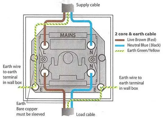
When installing a two-position circuit breaker, ensure that each terminal is securely connected to the corresponding conductor. This setup allows the simultaneous control of two separate circuits, making it ideal for managing high-voltage appliances or equipment with dual power sources. For optimal performance, use appropriately rated wires for both the load and the input terminals.
Key Considerations: Begin by identifying the proper location for mounting the device, ensuring there is enough space for cable entry and clearance. The two terminals on the left should be connected to the incoming power, while the right terminals will manage the outgoing current. Always double-check that the power supply is turned off before proceeding with any connections.
Important wiring steps include: ensuring that the live and neutral wires are correctly aligned with the device’s corresponding contacts. Miswiring could lead to hazardous situations, such as short circuits or overheating. Additionally, ensure that the mechanical parts of the breaker are free from obstructions for smooth operation and longevity.
Once connected, test the device using a multimeter to verify correct operation. Ensure that when the mechanism is engaged, the power flow is properly routed to the circuits. Regular maintenance and testing will help extend the life of the component and ensure safety during use.
Wiring and Connection Overview for a Dual-Control Circuit
For a circuit requiring independent control of two separate live wires, a two-position actuator with four terminals is essential. This setup allows both live connections to be switched on or off simultaneously. Each terminal has a clear function: two for input, two for output. Proper connection to the power source and load is critical to ensure safety and functionality.
The common terminals should connect to the power input, while the other two terminals connect to the load. Make sure that the actuator is rated for the specific voltage and current of the circuit. Incorrect matching may cause overheating or failure. For optimal performance, ensure the actuator is securely mounted, and all wires are tightly connected to prevent loose contacts.
In some applications, a schematic with labeled terminals for clear understanding might help visualize the connections. If you’re unsure, always consult the product’s manual or a qualified electrician for guidance on wiring procedures.
Wiring a 240V Circuit Disconnect
To wire a 240V circuit disconnect, ensure that the power is turned off at the breaker box before beginning. Start by identifying the two live wires (typically black and red) and the ground wire (green or bare). Connect the live wires to the two terminals on the device, making sure they are securely tightened. The ground wire should be attached to the grounding terminal, usually located at the bottom or side of the unit.
For the neutral wire, if present, ensure it is not connected to the device unless the circuit specifically requires it. In most 240V installations, the neutral is not used. After wiring the terminals, ensure all connections are tight and there are no exposed conductors that could lead to short circuits or electrocution.
Finally, install the cover plate and mount the unit in a convenient, accessible location. Turn the power back on at the breaker panel and test the operation of the circuit. Use a multimeter to verify proper voltage at the device’s terminals before final use.
Identifying the Components of a Two-Circuit Control System
To correctly identify the elements in a two-circuit control system, focus on the following components:
- Power Input Terminals: These are where the incoming electrical current connects, typically marked with an ‘L’ or ‘Live’ label.
- Output Terminals: These terminals supply current to the connected loads, usually marked ‘O’ or ‘Out’.
- Common Terminal: A shared connection that links the two control paths together. It is essential for balancing the current flow across circuits.
- Contactor Mechanism: This part controls the flow of electricity by making or breaking the electrical connection between terminals based on the activation of the mechanism.
- Terminal Screws: These screws secure the wires in place at each terminal point, preventing disconnections or short circuits.
- Actuator: The component that physically moves to change the electrical connection. It can be toggled by manual or remote control.
- Ground Terminal: Provides a safe path for current to return to the ground in case of a fault, preventing electrical hazards.
Understanding these key components is essential for troubleshooting, replacement, or system design. Accurate identification ensures proper wiring and enhances safety.
Common Issues in Multi-Position Circuit Control Schematics and Solutions
Ensure proper orientation of components. Incorrectly wiring the terminals can cause malfunctions or failure to control circuits as expected. Always refer to the manufacturer’s wiring guide to verify the correct connections.
Overloading the mechanism is a frequent issue. When too many devices or high-power appliances are connected, it can lead to overheating or complete failure of the mechanism. Be mindful of the current ratings and avoid exceeding them. Use an appropriate fuse or breaker to protect the system.
Misidentifying the terminals is another common error. Marking inconsistencies or confusion between input and output terminals often result in incorrect operation. Double-check the terminal labels and cross-reference with a reliable reference source.
Loose connections can also cause intermittent issues. Over time, vibrations or frequent use may loosen terminal screws. Regularly inspect connections for tightness and use proper tools to ensure they are secure, minimizing the risk of arcing or short circuits.
Compatibility with other components should be checked before installation. Using incompatible parts or outdated mechanisms can cause failure to operate or safety risks. Confirm that all components in the system match the specified standards for voltage, current, and installation requirements.
Overcomplicating the layout can lead to confusion and installation errors. Simplify the circuit design and avoid unnecessary complexity that may lead to miswiring or poor performance. Stick to clear and concise schematics that align with practical requirements.