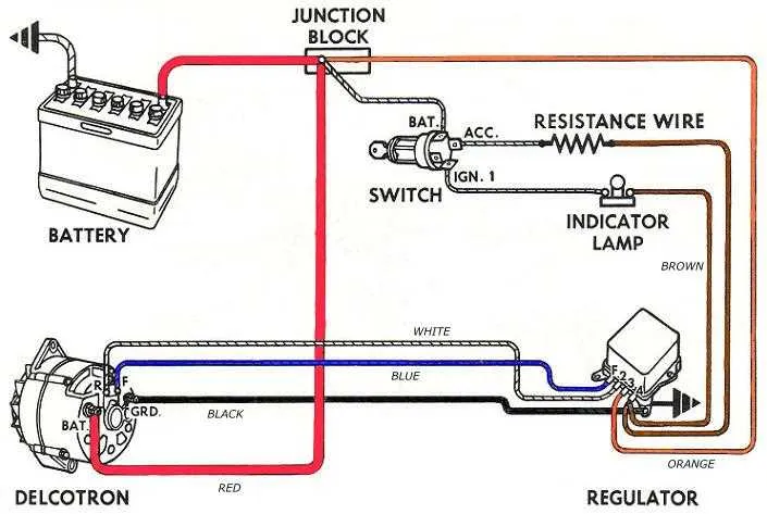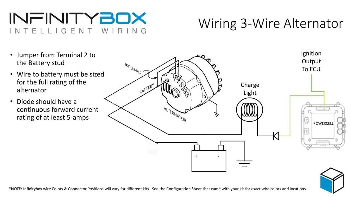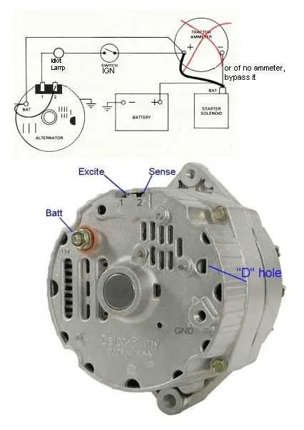
If you’re working with a 3-phase generator that uses a three-terminal voltage control system, it is crucial to understand the specific connections to ensure proper functionality. Each component plays a unique role in regulating the output, and incorrect assembly can lead to malfunction or inefficient operation.
Start by connecting the first terminal to the positive output, ensuring it is securely fastened to avoid any fluctuations. The second connection should go to the field coil, which allows the unit to manage output under varying loads. Finally, the third terminal must link to the ground or chassis, completing the loop for safe operation.
To maintain optimal performance, it’s recommended to use high-quality connectors and check for any signs of wear or corrosion periodically. Additionally, pay attention to the voltage at each point to confirm that everything is within acceptable limits. If you’re unsure, always refer to specific technical manuals for calibration details.
While setting up, always prioritize proper insulation for safety. Improper handling could cause overheating, which may damage the system. Following these guidelines will help you create a reliable connection and ensure the longevity of your equipment.
3-Wire Setup for Voltage Control System
For effective installation, connect the three key terminals to ensure proper voltage regulation. The first connection should be to the battery’s positive terminal, providing the necessary power source for the system. The second terminal must be connected to the sensing input, typically leading to the vehicle’s electrical system to monitor voltage levels. Lastly, the third terminal controls the ground, ensuring the system is properly earthed for safe operation.
Key Connections:
1. Power source (positive) – Ensures charging functionality.
2. Sensing input – Monitors the voltage level and adjusts accordingly.
3. Ground terminal – Necessary for safe operation by maintaining an effective earth connection.
Check all connections for tightness and security to avoid voltage fluctuations or system malfunctions. Proper grounding ensures that the voltage control unit responds accurately to the demands of the electrical system.
Always use high-quality connectors to prevent corrosion and ensure long-lasting performance. The power supply should be stable and free of intermittent disruptions to maintain the efficiency of the charging system.
Understanding the Three-Wire System: Key Components and Functions

The three-wire system operates on three essential connections: the positive output, field control, and ground. These connections play critical roles in ensuring the proper functioning of the charging unit in an engine-powered system. Proper identification and understanding of each component are crucial for troubleshooting and maintenance.
The positive output, typically connected to the battery, delivers current from the generator to recharge the battery. This is the main source of power for the electrical system once the engine is running. It ensures that the vehicle or machinery continues to operate smoothly even when the engine isn’t actively generating power.
The field control connection regulates the magnetic field intensity, which directly affects the power output. By varying the current in the field windings, the system adjusts the voltage produced by the generator. This allows for efficient charging, even as engine speeds fluctuate. A properly functioning control component ensures stable output across a range of conditions.
The ground connection serves as the return path for the electrical current, completing the circuit. A solid and stable ground is necessary for the system to work efficiently. Any issues with the ground can lead to irregularities in the power output and cause performance problems.
Maintenance and troubleshooting of this system require checking each of these three critical connections for continuity and proper function. Loose or damaged terminals, faulty components, or issues with the grounding can lead to significant problems in power generation and charging capacity.
Wiring a 3-Wire Generator with Built-in Control: Step-by-Step Guide

Begin by connecting the main power output terminal to the battery positive terminal. This provides the essential link for generating electrical current. Use an appropriately gauged conductor for the best efficiency and safety.
Next, the connection from the control terminal to the ignition switch should be established. This ensures the proper start-up sequence for the device, activating the current flow when the engine is running.
Ensure the ground terminal is securely connected to the chassis or engine block. This is crucial for maintaining the system’s integrity and ensuring that the device functions correctly during operation.
Important Tip: Double-check all connections for tightness and corrosion-free contacts before powering up. Any loose connection or poor contact can lead to reduced performance or malfunction.
After securing all terminals, test the setup by turning on the ignition. The generator should begin charging the battery as soon as the engine starts, provided all connections are made correctly.
Note: Always use protective gloves and safety equipment when handling electrical components to avoid injury or damage to the system.
Troubleshooting Common Issues in 3-Wire Charging Systems with Built-in Regulation
To address common issues with a three-wire charging system, follow these steps to ensure proper functionality:
- No output voltage: Check the connection to the battery and ground. A loose or corroded terminal can prevent charging. Use a multimeter to confirm voltage at the output terminal. If there’s no reading, the issue may lie with the voltage sensing or charging circuit.
- Low or fluctuating voltage: Ensure the connection between the sensing terminal and the system is clean and tight. Fluctuations may indicate a poor ground or interference in the signal line.
- Overcharging: If voltage exceeds 14.5V, inspect the control circuitry. Faulty components, such as a damaged voltage control module, can cause excessive output. Check for damaged diodes or components in the regulation path.
- Overheating: This is often a result of poor air circulation or excessive load. Verify that the cooling system is functional, and ensure the charging unit isn’t working too hard by checking current draw and operational environment.
- Intermittent charging: Check for loose or worn-out connections. Especially inspect the positive and negative terminals, as intermittent power can result from faulty contact.
- System not charging after starting engine: Test the activation signal. If the start-up sequence is incomplete or missing, the unit may not initiate charging. Ensure proper voltage is supplied to the activation terminal immediately after the engine starts.
Routine inspection of connections, system integrity, and component condition is essential for smooth performance and reliable operation.