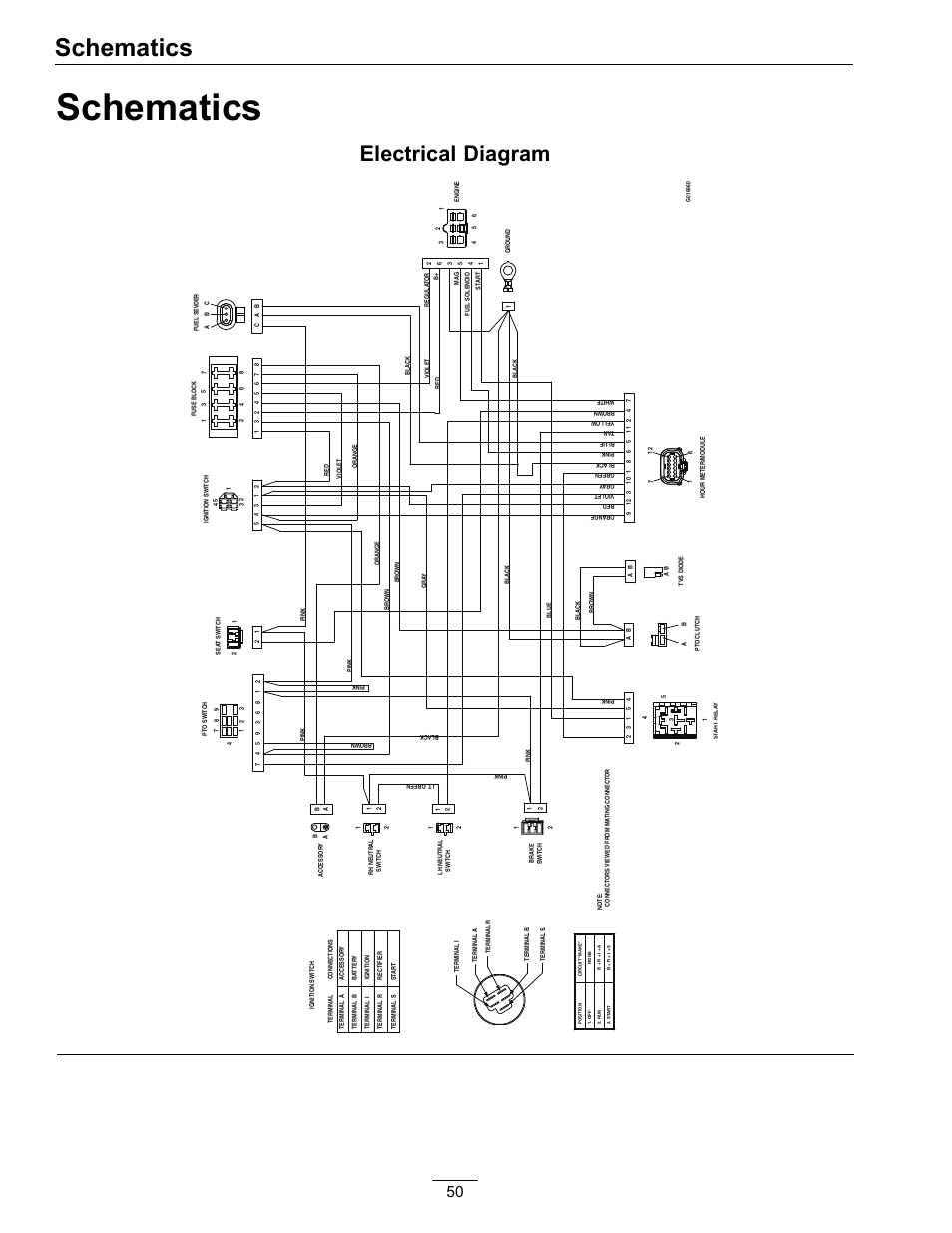
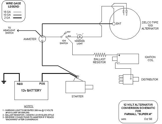
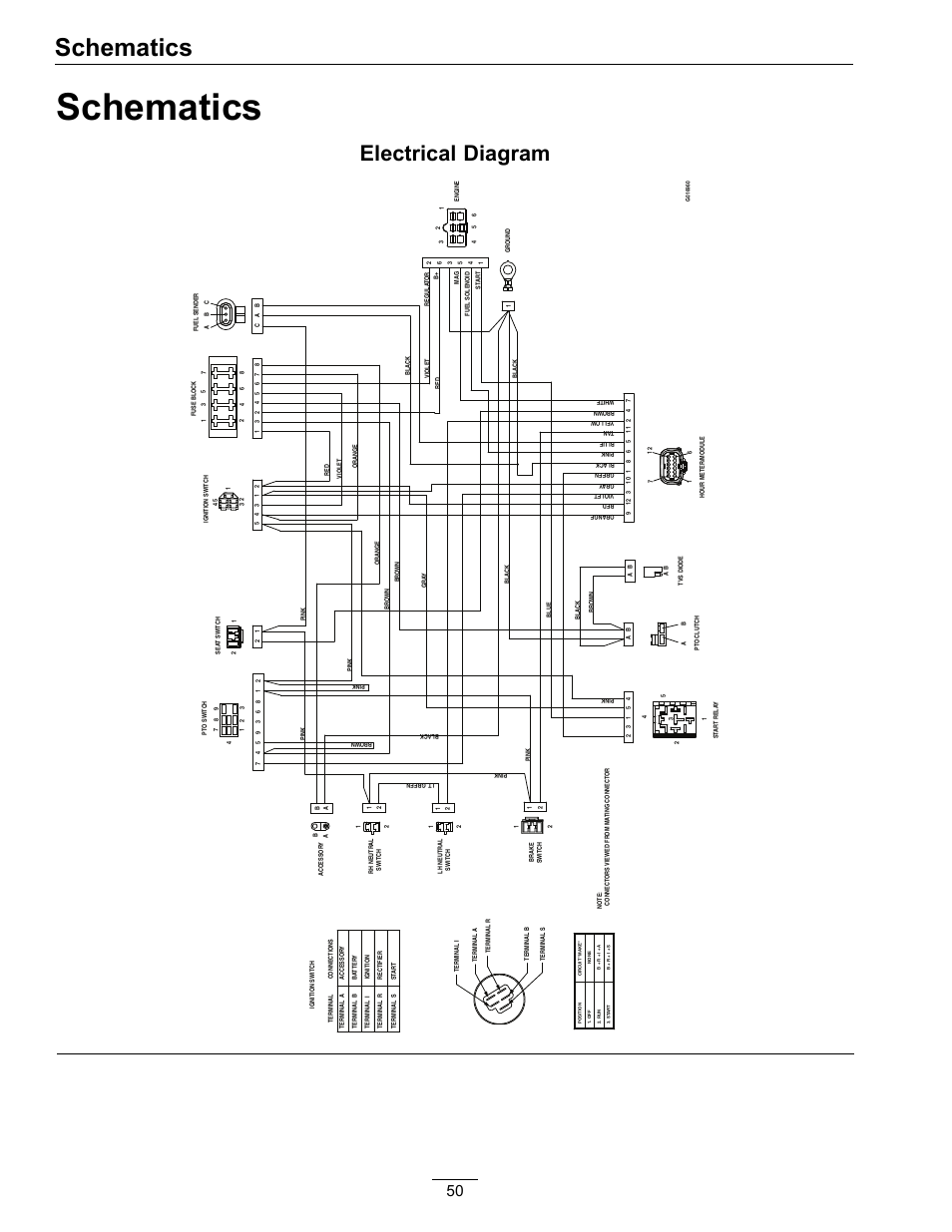
Motor – Free-wheel Main Wiring Diagram VR2 and RNET Check Battery Wire Harness Please read and follow instructions in this service manual before Are all necessary power components installed and connected? .

V/m is: a right- handed mounted joystick system, 18” seat width, 18” seat depth. Motor – Free-wheel Main Wiring Diagram VR2 and RNET Check Battery Wire Harness Please read and follow instructions in this service manual before Are all necessary power components installed and connected? .
V/m is: a right- handed mounted joystick system, 18” seat width, 18” seat depth. Your Permobil is designed to give you highest possible comfort and safety and Duke Drive . Always keep these operating instructions handy in connection with your ..
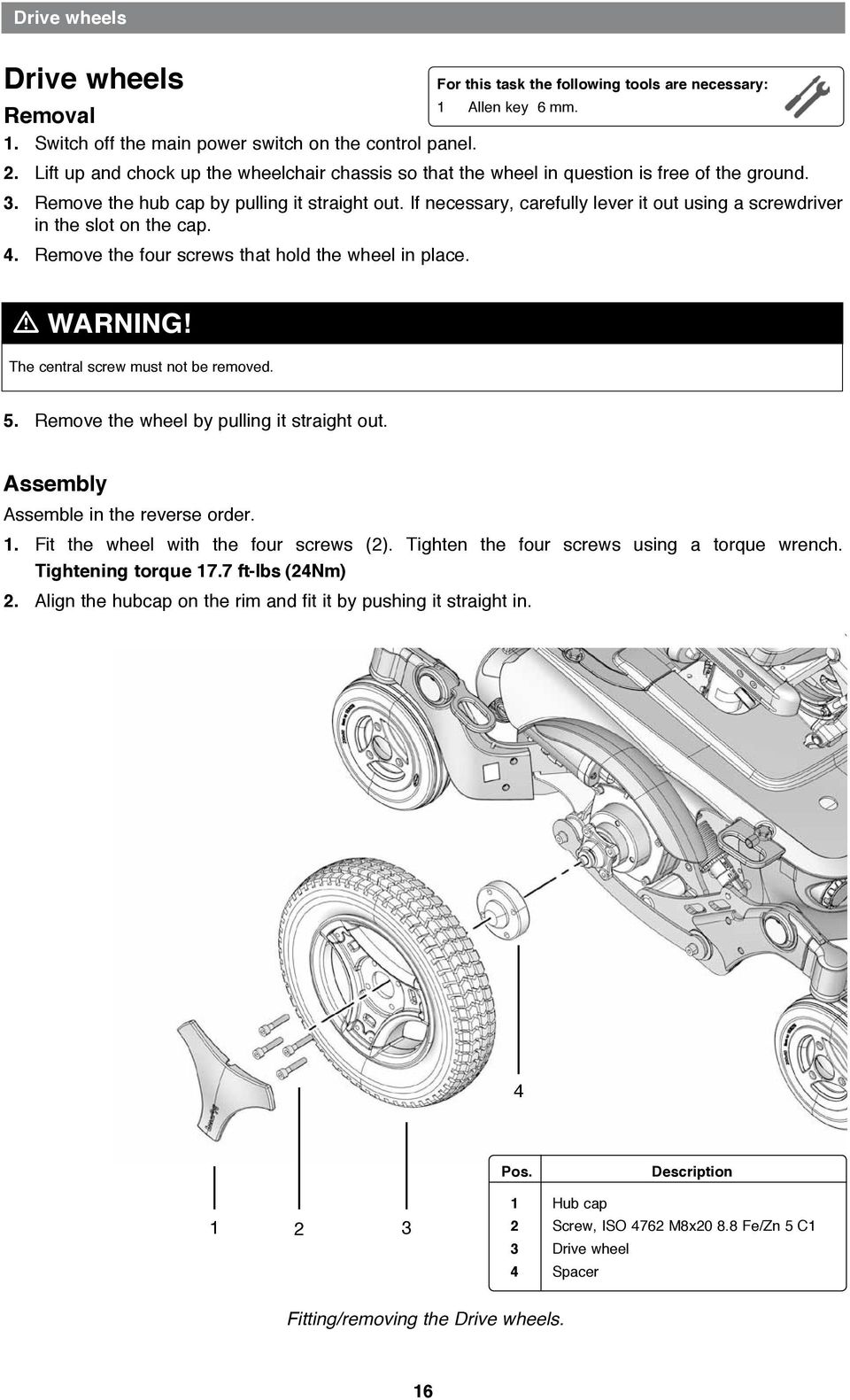
The wheelchair’s drive wheels, are available with pneumatic or Flat- Free . There is a risk of pinching accidents when using the electrical seat func-. Products 62 – 67 2 Chair Model and Colors CHOOSE BASE: I M Base Corpus 3G Price Please select caster size and drive wheel type: 6″ Casters: 8″ Casters: Flat free drive tires: Programming Key for R-net – Permobil Version Stealth BPAP Vent ..
19 Other Items Additional Order Instructions: Chair Order Policy: You. 4 Permobil K/C Power Wheelchair Produced and published by Permobil AB, Sweden .
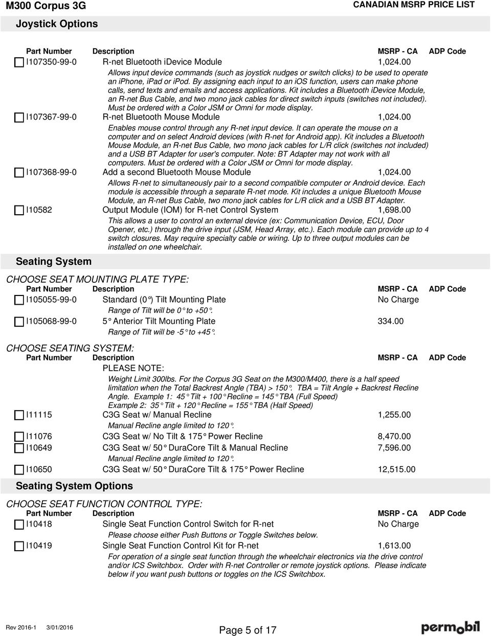
M300 Corpus 3G. Dealer Information. Client Information. Client Measurements
10 Safety Instructions Safety Instructions m WARNING Operation Permobil . Connecting any unapproved electrical or electronic devices to the ..
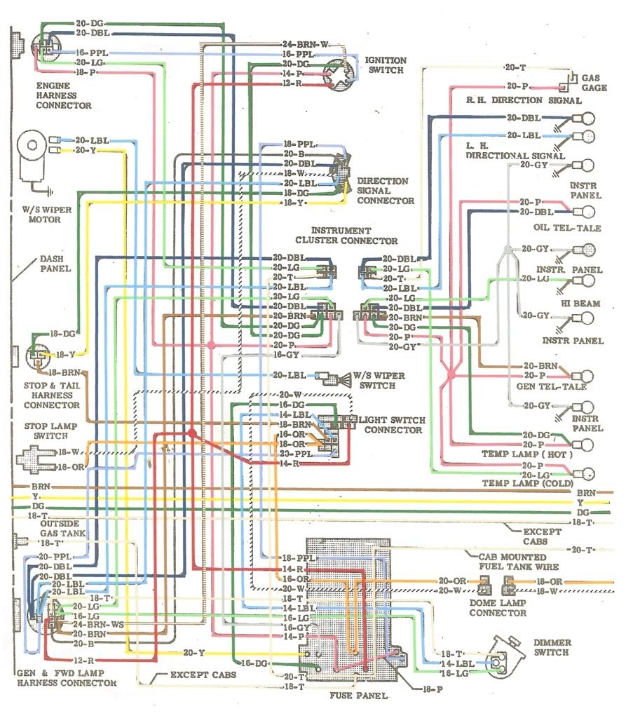
Description Block Diagram Main Parameters Circuit Diagram Installation and.Main harness has another ring lug for grounding at the RF corner of the body. This (originally) attaches with a hex nut to an extra length fender bolt, second bolt up from the air pan in front of the radiator.
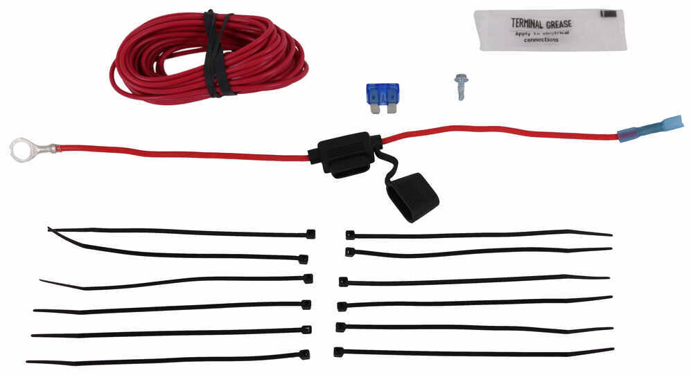
Side harness has a ring lug to ground on a frame tab bracket underneath and . Basic Steps for Wire Harness Building – Part I. Posted on August 31, The following points showcase the basic requirements and steps to build a wire harness.

Create a Wiring Diagram: Cover the Wire: Once the above step has been completed, pull the heat shrink over the crimped wire edge and terminal seam. Ensure that the tubing closes.
Wiring Installation Instructions For steps operated by a Door Switch and Power Switch with Control # 01/05 Kwikee Kwikee # Rev. 0A Installation Instructions Step 1) Wrap electrical tape around the black plastic loom of the wiring harness every “.

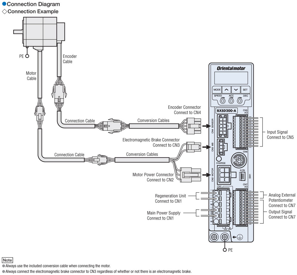
Step 2) Route the wiring harness from the vehicle battery to the step with the. This connection is made slightly more The basic wiring diagram is shown below in Figure 2. Figure 2 Diagram for Minimal Wiring Configuration The Coils of the stepper motor are labeled A and B respectively.
These connections are made as shown to the board. These connections are what are used to step the magnet inside of the stepper motor. Save stepper motor wiring harness to get e-mail alerts and updates on your eBay Feed.
+ Items in search results. See search results that fit your vehicle. Fast & Free Shipping!
Brand New. $ List price: Previous Price $ Buy It Now.
Free Shipping. 7% off.
29 new & refurbished from $M Corpus 3G. Dealer Information. Client Information.
Client Measurements – PDFHow to Wire a Stepper Motor | Simply Smarter Circuitry Blog