Essential Component Layout for the Appliance
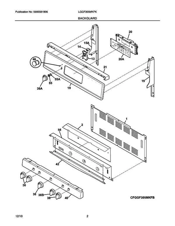
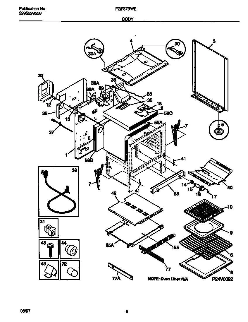
Locate the burner assembly by referencing the top view schematic, which details each ignition element, burner cap, and associated gas valve. Understanding this layout allows precise identification and replacement of worn or malfunctioning pieces.
Surface Elements and Their Functions

- Heating elements: Typically coil-type or sealed units, these deliver heat to pots and pans. Match the exact wattage and connector type when sourcing replacements.
- Control knobs: Interface with the regulator switch; ensure proper fit to avoid control issues.
- Ignition system: Includes spark modules and electrodes; verify spark gap for optimal performance.
Oven Interior and Mechanical Assembly

The oven cavity comprises multiple parts critical for uniform heat distribution and safe operation:
- Heating elements: Bake and broil units, identifiable by shape and connection points.
- Thermostat sensor: Monitors temperature; replace if the oven temperature reading is inaccurate.
- Door seal: Ensures heat retention; a damaged seal results in energy loss and uneven cooking.
- Control board: Manages timing and temperature; diagnose faults through error codes if available.
Recommendations for Replacement
- Use model-specific part numbers for ordering to guarantee compatibility.
- Refer to manufacturer-issued component layouts or exploded views for accurate assembly guidance.
- Document the disassembly process with photos to assist reassembly and prevent mistakes.
Where to find and interpret replacement part numbers on appliance schematics
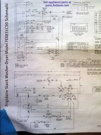
Locate the alphanumeric codes directly adjacent to each component illustration in the technical drawing. These identifiers usually consist of a combination of letters and digits, representing specific item references used by manufacturers and suppliers.
Use the legend or key section, typically positioned at the bottom or side of the schematic, to cross-reference these codes with detailed descriptions, model compatibility, and ordering information.
Note that some references may include suffixes indicating variations or subcategories of a main component, such as heating elements versus control knobs. Always verify these distinctions before making a purchase.
Online parts catalogs and official service manuals often provide exploded views with matching reference numbers. Comparing these resources against the illustration ensures correct identification of replacement units.
When in doubt, consult the component list linked to the drawing, which breaks down each number into its corresponding item name, part number, and function within the appliance system.