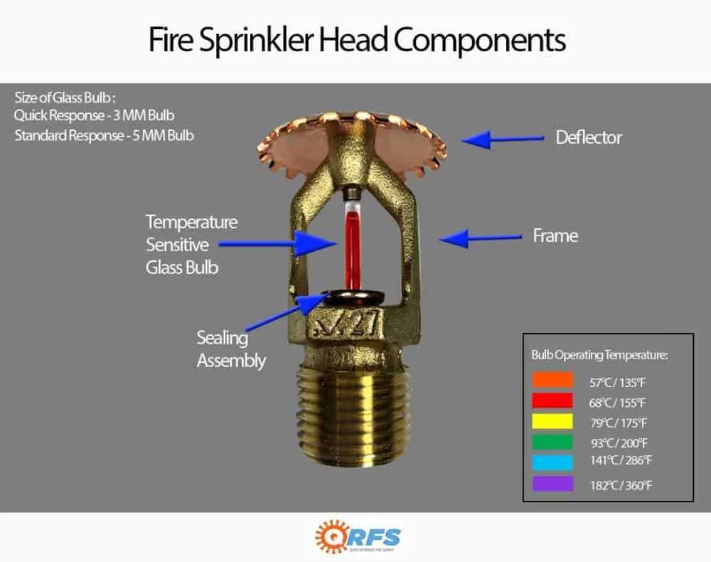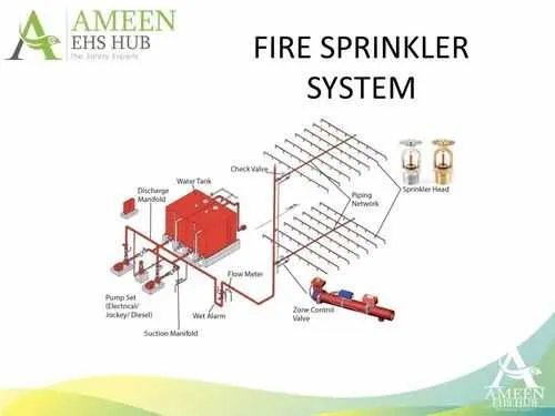
Ensure that your building’s water suppression network is designed with clear and efficient component placement. Proper positioning of nozzles, pipes, and valves is crucial for optimal coverage and reliability. The layout should prioritize accessibility for maintenance and testing, reducing the risk of system failure during emergencies.
Choose pipe routes carefully to avoid unnecessary bends or long distances, which can impede water flow. The layout should be designed to allow for easy identification of any leaks or blockages, ensuring quick and effective repairs. Consider using zone-based segmentation for better control over different building areas.
Incorporate a clear plan for integrating pressure regulators and control valves, ensuring consistent performance throughout the structure. Accurate placement of these components is vital for uniform water distribution, reducing the chance of system malfunctions. A robust setup will enhance both safety and performance, especially in large buildings with varying floor heights.
It is essential to test the system regularly, ensuring that each part operates as intended. Monitoring the flow rate and pressure at key points will help identify potential issues before they become critical. Proper labeling and clear schematics are necessary for efficient troubleshooting and maintenance tasks.
Water-Based Extinguishing Network Layout

Ensure all devices are connected to the main control valve, which should be easily accessible for emergency use. Proper spacing between each activation unit is critical to ensure rapid coverage in case of activation. Check that the distribution pipes are sized based on the expected water pressure and flow rate, as inadequate pipe dimensions will delay response time.
Activation Points: Devices should be strategically placed in areas with high fire risk. Common placements include ceilings of kitchens, storage areas, and electrical rooms. Verify that each point has a clear line of sight to the ceiling or the target area to avoid obstructions that could impede response.
Water Supply: A reliable water source is necessary for efficient operation. In case of a main supply failure, consider having an auxiliary tank or backup pump. The capacity of the water supply should be evaluated based on the total number of activation units and expected consumption during an emergency.
Pressure and Flow Checks: Pressure gauges must be installed to monitor the network’s performance. A constant pressure level should be maintained to guarantee that all activation points function properly when needed. Periodic flow tests are recommended to ensure water distribution remains consistent across the entire setup.
Installation Standards: Follow the guidelines set by local regulations for pipe material, installation angles, and activation unit specifications. Regular inspections and maintenance are required to ensure compliance and proper functionality, especially after construction or renovations.
Note: Regularly review and update the setup to meet evolving safety codes and performance standards to ensure optimal effectiveness during a critical event.
Designing a Suppression Network: Key Components and Layout
Begin with the identification of water supply requirements. Ensure that the pressure and flow meet the standards for optimal distribution. Use pressure-reducing valves where necessary to balance flow rates across the coverage area.
Incorporate network pipes with appropriate diameters, typically ranging from 1 to 6 inches, depending on the coverage area and building layout. The pipe layout must provide the most efficient distribution, considering the geometry of rooms, corridors, and ceilings.
Place discharge nozzles strategically to cover each zone effectively. The distance between them should follow local regulations, but typical spacing is between 8 to 12 feet. Ensure that each nozzle’s coverage area meets the minimum specified volume of water discharge.
Include a control valve to regulate water flow, ensuring that it is easily accessible for maintenance and emergency operations. This valve should be paired with a monitoring system that tracks the operational status in real-time.
Install a reliable detection mechanism to trigger activation. This may involve heat detectors or smoke sensors linked directly to the suppression mechanism for immediate response.
Consider redundancy for critical components, including backup power for control panels and pressure switches. Evaluate the use of a manifold for connecting multiple water sources to guarantee continuous supply during emergencies.
Understanding Water Supply Requirements for Sprinkler Systems
The water supply must meet specific pressure and flow rate criteria to ensure optimal performance of the automatic suppression setup. A reliable water source should provide sufficient volume and pressure to cover the entire protected area without interruption. The required pressure typically ranges from 30 to 50 psi at the most distant point of the network, depending on the design specifications and the type of suppression equipment used.
It is recommended to maintain a minimum flow rate of 30 gallons per minute per head. The total required flow depends on the number of heads that will be activated simultaneously. The water source should be capable of providing the necessary flow for the duration specified by the local authority or national code, usually for at least 30 minutes during an emergency event.
Regularly inspect the water supply to ensure it remains free from obstructions and that the pressure is consistent with the design specifications. Backup water sources, such as storage tanks or pumps, should be considered for situations where the main supply may fail.
Considerations for calculating flow and pressure include pipe diameter, friction losses, and elevation changes, all of which influence the efficiency of water distribution. The use of pressure-regulating valves and monitoring equipment can also improve performance and reliability during an activation.
Common Water Distribution Network Design Errors and How to Avoid Them
Ensure clear zoning to prevent overlapping coverage areas. This minimizes redundancy and ensures optimal water distribution efficiency.
- Misplacement of control valves can lead to inefficient water flow. Ensure precise valve positioning to guarantee effective operation.
- Underestimating pressure requirements results in inadequate coverage. Perform thorough pressure testing to confirm that all areas meet minimum standards.
- Failure to account for obstructions, such as beams and walls, may disrupt water delivery. Always factor in structural elements during layout planning.
- Incorrect pipe sizing can reduce effectiveness. Perform accurate calculations based on the volume of space and expected demand.
- Improper spacing between emitters may cause uneven coverage. Adhere to manufacturer guidelines for correct emitter placement and spacing.
Always conduct thorough reviews of the final layout to verify it meets all operational and regulatory standards.