If you’re working on the electrical setup of your heating system, it’s crucial to ensure proper connections for reliable performance. Start by identifying the main components that control the flow of power and their role in the overall system. Key parts like the thermostat, ignition system, and safety sensors should be correctly wired to avoid malfunction.
Each component is linked through a series of connectors, and the correct order and position of wires ensure that the system runs smoothly. Pay close attention to the sequence of connections for elements like the thermostat and safety switches, as incorrect wiring can lead to overheating or failure to activate the system.
Test continuity at each step of the setup to verify that power flows as intended, and look for any signs of wear or damage in the connections. If the system is not operating as expected, checking for loose or shorted wires can often resolve issues before they become more complex.
For more advanced troubleshooting, review the signal paths for different stages of the heating cycle. Ensure that components like the flame sensor and pressure switch are receiving the correct voltage at the right times. This will help maintain efficient and safe operation of the system.
Remember, it’s better to consult a professional technician if you encounter persistent electrical issues that go beyond basic troubleshooting. The integrity of the electrical system is key to maintaining both efficiency and safety in your heating setup.
Understanding the Electrical Connections for Heating Systems
Ensure power is disconnected before handling any electrical components to avoid injury or damage. Start by identifying the power input terminals and confirming the voltage ratings for compatibility with the system’s requirements.
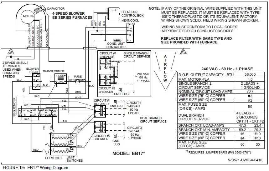
The primary relay connects to the transformer and the main heating element, usually via a low-voltage control circuit. Ensure that the wire connections to these parts are secure and correctly matched according to their designated positions.
Double-check the fan motor wiring. This component often requires a dedicated connection for optimal performance. If it’s wired incorrectly, the fan may not activate when needed, leading to overheating.
For systems that involve a temperature sensor, confirm that the sensor wiring is correctly routed to the thermostat. Any misalignment in the circuit can cause inaccurate readings and disrupt heating cycles.
Review the limit switch connections carefully, especially when dealing with multiple phases or advanced components. An incorrect connection can lead to system shutdowns or improper responses to temperature changes.
After wiring the system, perform a continuity check using a multimeter to ensure all circuits are properly connected and there are no shorts or open circuits that could compromise performance.
Understanding Key Connections in Furnace Control Board Wiring

Ensure proper connection of the power supply terminals to avoid short circuits and malfunctioning of the system. Always confirm that the neutral and live wires are correctly placed, as incorrect connections can lead to electrical failures.
The ignition system requires a solid link between the ignition control and the heating element. Double-check this connection to maintain efficient ignition timing and avoid delayed starts. A loose connection can cause intermittent heating performance.
Verify the sensor connection for temperature regulation. A properly attached sensor wire ensures accurate room temperature readings and stable operation. Faulty connections can cause erratic heating cycles.
The connection to the fan motor should be carefully examined for any signs of wear or corrosion. Make sure that the motor terminals are tightly fastened to prevent erratic fan behavior or failure during operation.
For safety, check the grounding terminal. A solid ground connection is essential to protect the system from electrical surges and to avoid potential hazards.
Troubleshooting Common Wiring Issues in Heating Systems
Start by checking the power supply to the system. If no response is observed, confirm the main circuit breaker is on, and the transformer is receiving input voltage. A voltage drop or inconsistent power can cause malfunctions. If the voltage is unstable, inspect the connections to ensure they are tight and free from corrosion.
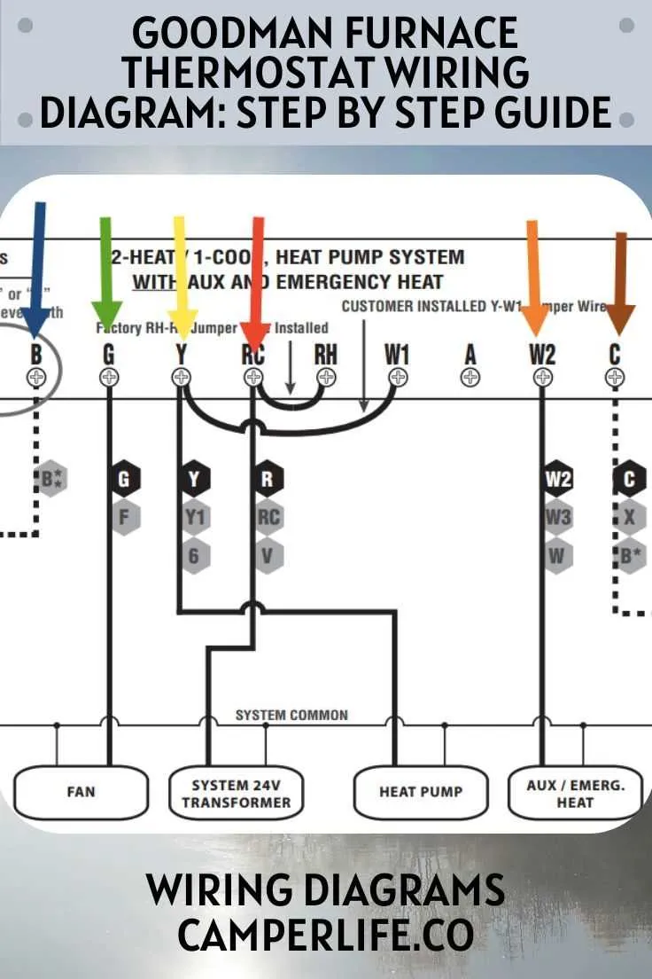
Examine the connections to the thermostat. A loose or damaged connection can prevent communication with the main unit. Verify continuity across all terminals. If readings are inconsistent, reattach or replace the wires as needed.
If there are issues with the igniter or blower motor, inspect the connections leading to these components. Verify that no wires are shorting or showing signs of wear. For any component malfunction, test the system for continuity and replace any faulty parts that affect the operation.
Look for any signs of overheating in the terminal connections. Discoloration or melted insulation indicates excessive current flow, potentially caused by loose connections or an overdrawn load. Tighten and replace any worn connections to prevent further damage.
If the system fails to activate despite power being present, check for issues with the relay and the signal path. A faulty relay can block signals from activating the heating unit. Measure the relay’s continuity and replace it if necessary.
Step-by-Step Guide to Correcting Wiring Errors in Furnace Control Boards
Start by turning off the power supply to prevent electrical hazards.
Check for visible signs of damage, such as burnt components or frayed connections. Inspect each terminal and connection point carefully.
Follow this procedure to identify and correct issues:
- Verify the power source and ensure the voltage matches the specifications required for the system.
- Confirm that all connections are securely attached. Loose terminals can lead to malfunctions.
- Examine each wire for wear, ensuring there are no exposed copper strands that could cause short circuits.
- Use a multimeter to test continuity across connections. Any open circuits must be addressed immediately.
- Trace each wire from start to end, ensuring the path follows the correct sequence according to the manufacturer’s guidelines.
- If you find an incorrect connection, disconnect the relevant wire and reconnect it according to the correct schematic layout.
- For multi-wire configurations, ensure that each wire is placed in the correct terminal, following color codes and the provided documentation.
- After all corrections, restore power to test the system and ensure all functions operate as expected.
If the issue persists, consider replacing damaged components or consulting with a qualified technician for further inspection.