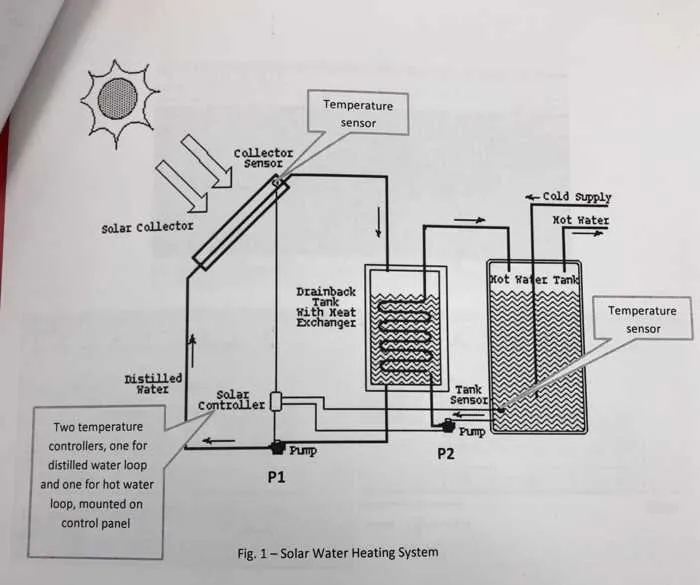
Begin with a closed-loop circuit powered by a storage cylinder and a heat source such as a gas boiler or electric heater. Ensure the reservoir includes an immersion element for backup and temperature maintenance during low-demand periods. Use thermostatic mixing valves to regulate outlet temperatures and prevent scalding.
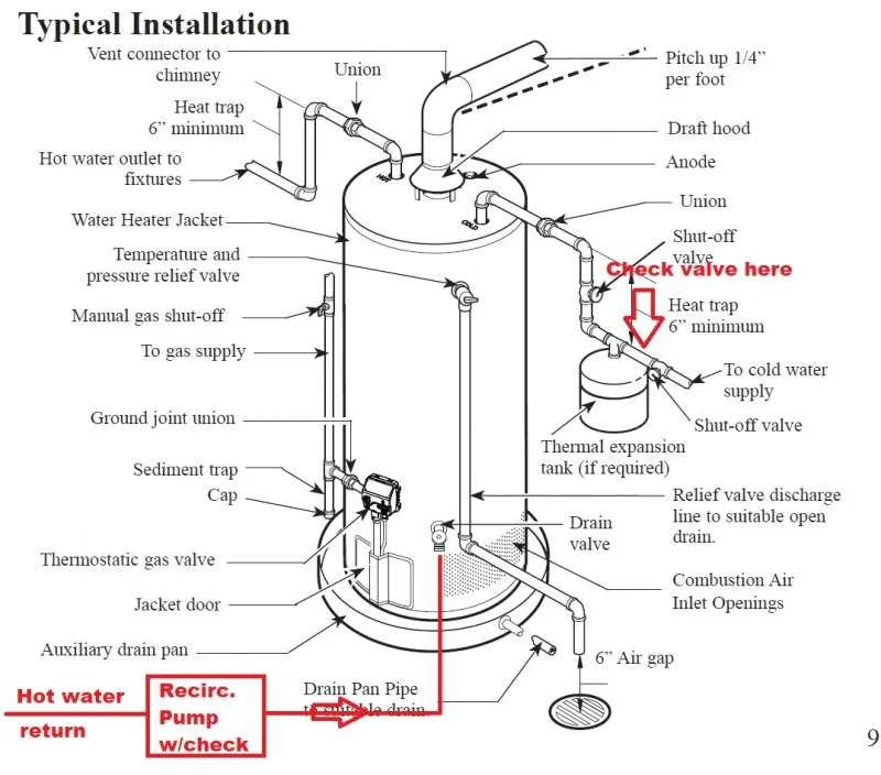
Place a circulation pump on the return line, just before the tank inlet, to maintain consistent flow across all outlets. Install non-return valves to prevent reverse flow, and isolate each branch with ball valves for easier maintenance and control.
For gravity-fed setups, position the header tank at least one meter above the highest outlet. Incorporate an air vent at the highest point of the pipework to eliminate trapped air pockets. All piping from the supply to outlets should be insulated to reduce heat loss.
Include an expansion vessel to absorb thermal expansion and protect joints from excessive pressure. For multi-storey buildings, zone the network by floor with individual control valves to optimize efficiency and pressure balance.
Layout of Domestic Heating Circuit

Use a closed-loop configuration with a primary loop connected to a boiler or heat pump, incorporating a pressure relief valve set to 3 bar and an expansion vessel sized at 10% of the total circuit volume. Position a circulation pump after the heat source and before any diverter valves to maintain optimal flow dynamics.
Include a thermostatic mixing valve at the distribution point to regulate outlet temperature, typically set between 50–55°C to prevent scalding. Install non-return valves at all branch connections to avoid backflow, especially when integrating solar thermal collectors or secondary loops.
Place air vents at the highest points and drain valves at the lowest to simplify maintenance. For multi-storey buildings, use zone valves controlled by programmable thermostats to separate levels and ensure targeted energy use. Lag all piping, especially in unheated areas, using insulation with a minimum thickness of 19 mm to reduce thermal losses.
How to Identify Key Components in a Domestic Hot Water Diagram
Start by locating the heat source–typically a boiler or immersion heater. It’s usually positioned near the base of the layout and connected to an energy supply line, such as gas or electricity.
Next, trace the primary cylinder or storage tank. This insulated vessel stores the warmed liquid and is often drawn as a large vertical or horizontal container. Look for temperature and pressure relief valves attached to its top or side.
Identify the circulation loop. Pipes leading away from the heating element and returning after passing through fixtures indicate active flow. The feed line delivers to taps and appliances, while the return loop helps maintain constant temperature.
Check for thermostatic mixing valves–devices that blend heated and cold input to prevent scalding. These are often placed just before distribution points.
Locate expansion vessels, which absorb pressure fluctuations. These are small, rounded containers typically placed near the heat source or storage unit.
Spot auxiliary features like check valves, isolating valves, and filters. These ensure safe, efficient operation and are commonly installed at key junctions or branch points.
Where to Place Valves and Sensors for Safe Operation
Install shut-off valves immediately after the main supply entry point to isolate the entire circuit quickly. Pressure relief valves must be positioned near the heating unit outlet to prevent overpressure risks.
- Temperature sensors should be mounted on the output pipe from the boiler or heater to monitor discharge conditions precisely.
- Flow sensors belong on the return line before the storage tank to detect circulation interruptions or blockages.
- Install check valves on all branches feeding distribution points to prevent backflow and contamination.
Automatic drain valves must be located at the lowest points of piping runs to evacuate trapped condensate or excess fluid effectively.
- Safety shut-off valves near thermostatic controls allow immediate flow interruption in case of abnormal readings.
- Place sensors inside insulated pipes to ensure accurate temperature measurement unaffected by ambient conditions.
- Pressure gauges should be installed before and after pumps to detect pressure drops indicating mechanical failures.
Valves controlling circulation loops must be accessible for manual operation and maintenance, typically near junction boxes or access panels.
How to Interpret Flow Direction and Pressure Zones on the Schematic
Identify arrows indicating the movement of the heated fluid through pipes; these show the exact path from the heat source to end points. Confirm the flow by tracing from the supply side to return lines, ensuring consistency with the installation layout.
Recognize pressure zones by noting locations of expansion tanks, pumps, and valves that create differences in hydraulic pressure. Higher pressure areas are typically near the boiler or heater, while lower pressure regions appear downstream, especially after control valves or elevation changes.
Use color coding or line thickness if available: thicker or red-toned lines usually denote supply routes under higher pressure, whereas thinner or blue-toned lines represent return paths under reduced pressure.
Analyze pressure gauges or numeric indicators placed along the layout to distinguish between primary and secondary loops. Pressure drops across components help verify correct flow direction and identify potential blockages or malfunctioning valves.
Check for balance valves or zone controls that regulate flow distribution; these elements mark boundaries between distinct pressure areas and affect overall circulation efficiency.