
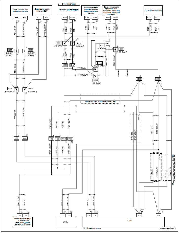
As shown in the Typical Wiring Diagram, the analog output signals originate F Instantaneous. Phase Time Overcurrent 1 Direction.
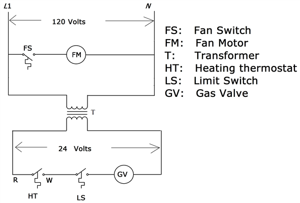
F GE In-Wall GE Smart Digital Timer • User guide • Download PDF for free and without registration!. The existing switch has a black (hot) wire and a load wire.
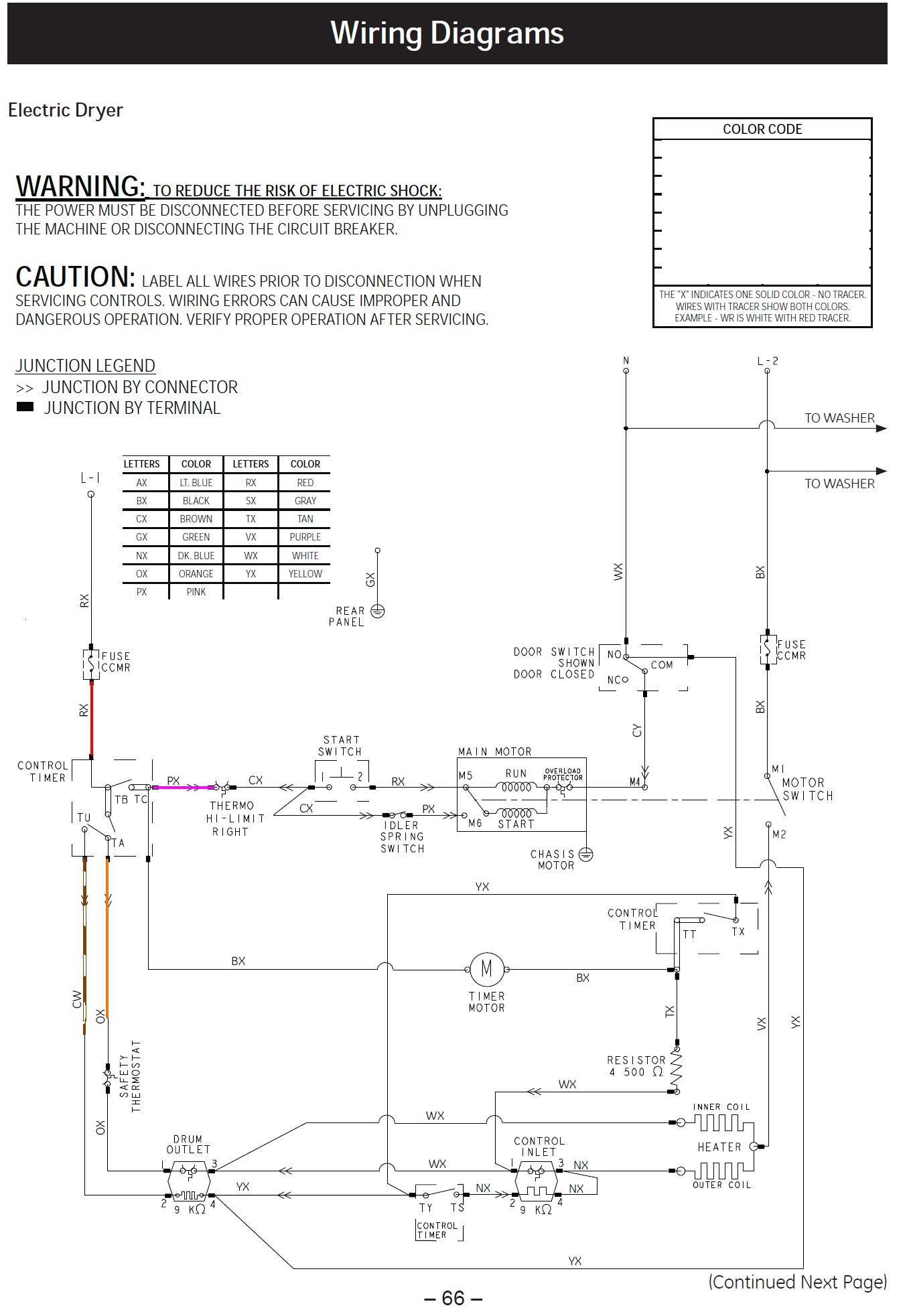
The new GE timer switch has a black (hot) wire, then a white wire, and a red. Read and download GE Timers InWall GE Smart Digital Timer GE user manuals, owners manuals, instructions, warranties and installation guides, etc.
I have a GE Smart digital timer model I had an look at all the wiring. Manual shows a black,red,white and green wire on the switch.Smart digital timer • Read online or download PDF • GE In-Wall GE Smart Digital Timer User Manual.
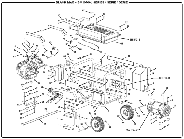
Manuals Directory schematron.org – online owner , the neutral wire can be found in the back of the wiring box bound in a wire nut. c) Connect the Hot/Live wire of Load to the Red wire from Timer.
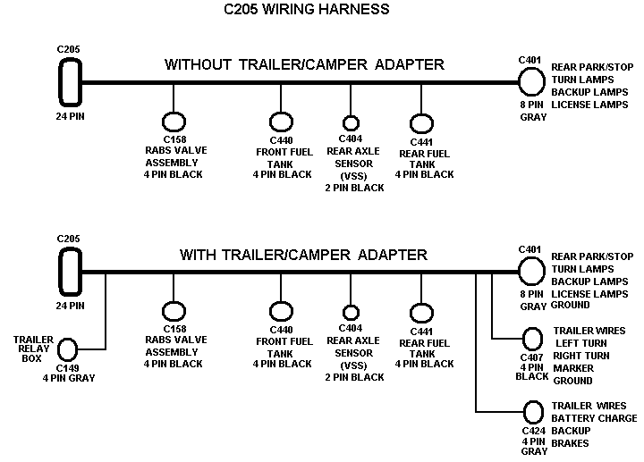
= Wiring Nut. Typical.
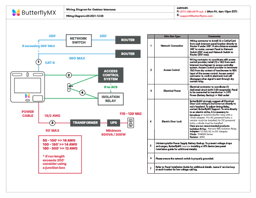
Industrial Solutions empowers smarter business operations by connecting equipment, software and services to protect, control and optimize assets within electrical infrastructures. Jan 02, · Wiring diagram for GE Mechanical Time Switch model I have 3 wires (hot, neutral, and ground) coming in for the hot water heater but it’s v but the GE Mechanical Time Switch wiring diagram shows 2 hot for the v wiring diagram.
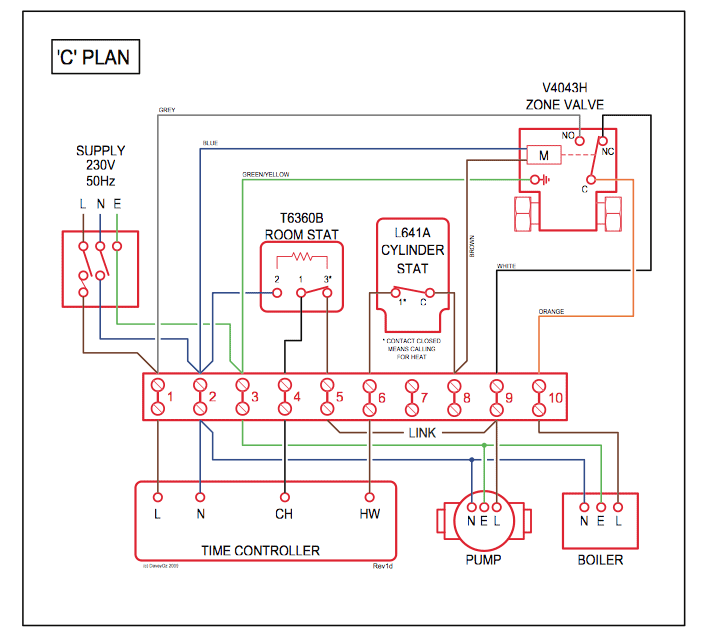
Read and download GE Timers InWall GE Smart Digital Timer Owner’s Manual online. Download free GE user manuals, owners manuals, instructions, warranties and installation guides, etc/5(K). Apr 28, · Wiring GE Smart Digital Timer to 3 way switch.
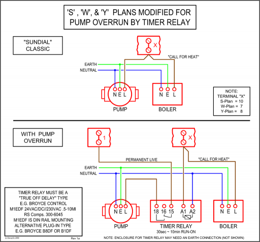
First off I have 2 switches located before the outside lights. I would like to put the timer on the first switch.Pdf Download | GE In-Wall GE Smart Digital Timer User Manual (1 page)GE In-Wall GE Smart Digital Timer User Manual | 1 page