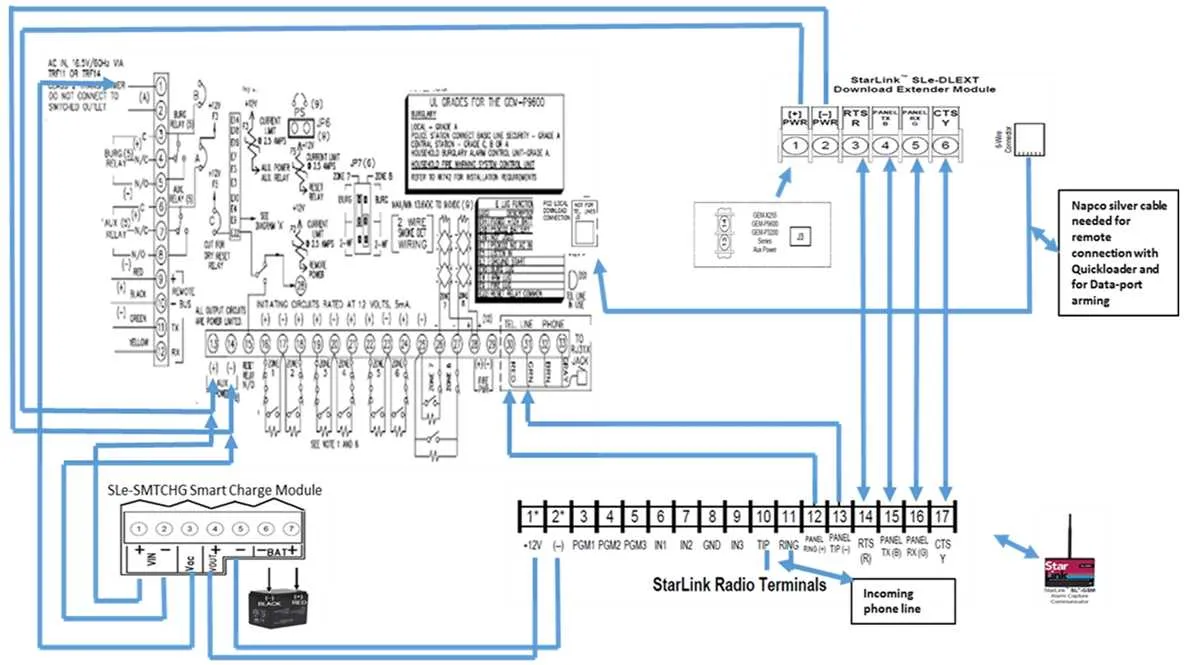
Begin by identifying the control module’s part number, typically found on the housing or through a diagnostic scan. Cross-reference this with the manufacturer’s service database to ensure the correct configuration scheme is used. Misidentification can result in short circuits or communication failure across the CAN bus system.
Use a multimeter to verify signal continuity before attaching any connectors. Power lines should show a steady 12V with ignition on, while ground lines must read zero resistance. Signal wires, particularly those linked to input sensors and output relays, should be tested for fluctuating voltage consistent with the module’s expected logic levels.
Position interface connectors away from high-temperature zones such as near the exhaust manifold or heater core. Excessive heat degrades insulation and can cause intermittent faults. If rerouting is necessary, employ heat-resistant conduit rated for automotive applications.
Color codes and pin numbering often vary between production years, even within the same model line. Always match each terminal to its assigned function based on verified technical documentation. For models with integrated keyless entry systems, data lines must be shielded to prevent RF interference.
Secure all harnesses with non-conductive fasteners and ensure no cables are under tension. Loose or stressed lines are a common cause of intermittent communication errors or complete signal loss, especially in high-vibration environments such as engine bays or wheel wells.
Efficient Control Unit Connection Layout
Start by identifying the control module’s terminal block, typically located beneath the dash or near the fuse panel. Use a multimeter to verify pin voltage before any attachment. Ground connections must be bolted directly to the chassis, no paint interference, to ensure signal stability.
When linking input leads, follow color codes strictly: red for power supply (usually 12V constant), black for ground, yellow or blue for signal triggers. Secure all joints with solder and heat shrink tubing to prevent corrosion and voltage drops.
For output channels, trace paths toward actuators or relays using stranded copper wire rated for automotive use, 16 AWG minimum. Route all paths away from ignition coils or high-current sources to prevent electromagnetic interference. Label each endpoint clearly to simplify future maintenance.
In multi-unit systems, include inline fuses rated 5A above operating load on every positive line. Avoid splicing into factory harnesses unless absolutely necessary–use dedicated ports or expansion connectors wherever available.
Test the setup under load before reassembly. If using a diagnostic port, confirm that signal pulses match manufacturer specs in both idle and active states. Always document your layout for future troubleshooting or upgrades.
How to Identify Power and Ground Connections in a GEM Remote System
Begin by locating the central control module housing the circuit terminals. Use a digital multimeter set to DC voltage to probe each terminal while the ignition is on. Terminals showing a steady 12V relative to chassis ground are typically power inputs.
To confirm ground points, switch the multimeter to continuity mode. Place one probe on the suspected ground terminal and the other on a bare metal surface of the vehicle’s body. A low-resistance reading (typically under 1 ohm) verifies a proper ground.
Always check for power supply fuses nearby; these are commonly rated at 10A or 15A and positioned between the control unit and the battery feed. Use color coding if present: red or orange wires often indicate constant power, while black or brown are usually grounded.
Use the connector pinout chart–if available–to cross-reference terminal numbers with their expected functions. Pay attention to voltage drop under load; any drop below 11.5V may indicate resistance in the supply path requiring inspection of terminals and wire crimps.
Never assume wire function based on color alone. Variations exist across models and years. Verify each lead empirically using measurement tools and confirmed schematics before making connections or replacements.
Wiring Color Codes and Pinout Reference for GEM Remote Modules
Always refer to the manufacturer’s pinout table before connecting any leads to avoid reverse polarity or signal conflicts. For most control interfaces, Pin 1 typically corresponds to Ground (GND), using a black conductor. Pin 2 is often assigned to +12V or +5V supply, generally marked red. Signal lines vary by protocol: for example, a green wire may carry CAN High, while white often represents CAN Low.
On a standard 6-pin connector, the typical configuration is as follows:
1 – GND (Black)
2 – Power (Red, 12V)
3 – TX (Yellow)
4 – RX (Blue)
5 – CAN High (Green)
6 – CAN Low (White)
Some modules use RJ-style connectors; in these cases, Pin 1 may not align with standard color assignments. Always validate with continuity testing before applying power. Avoid assuming uniformity across models–consult the module’s datasheet to confirm signal roles and voltage levels for each terminal.
Troubleshooting Common Faults in GEM Remote Installations
Start by verifying voltage levels at the input terminals using a multimeter; inconsistent readings often indicate grounding issues or poor connections.
- Loose terminal screws: Tighten all connections to manufacturer-specified torque levels. Inspect for signs of arcing or heat discoloration.
- Broken insulation: Examine conductors for nicks, abrasions, or exposed copper, particularly near bends or mounting points. Replace damaged segments immediately.
- Incorrect pin assignments: Cross-reference each connector’s pinout with the original spec sheet. Misaligned signal paths commonly disrupt communication between modules.
- Overloaded control lines: Measure current draw on control paths. Anything above rated capacity may indicate a shorted peripheral or defective relay coil.
- Voltage drop over long runs: If lengths exceed 30 feet, test voltage at both ends. Drops over 10% require gauge upgrade or installation of signal boosters.
For intermittent failures, use a data logger to capture real-time fluctuations under load. Focus on behavior during startup and shutdown sequences–most transient faults occur in these phases.
- Disconnect all endpoints except power and ground.
- Reintroduce each control unit sequentially while monitoring voltage and resistance.
- Document response changes to isolate faulty paths or components.
Finalize by applying dielectric grease to all terminals and sealing connections with heat-shrink tubing to prevent moisture ingress and oxidation.