
The ignition coil is an essential component in the ignition system of a GM vehicle. It converts the battery’s low voltage into the high voltage needed to create a spark in the spark plugs, which ignites the air-fuel mixture in the combustion chamber. Understanding the wiring diagram of the GM ignition coil is crucial for troubleshooting ignition system issues and making any necessary repairs.
The GM ignition coil wiring diagram typically includes details about the electrical connections and wire colors. It shows how the coil is connected to the battery, ignition switch, distributor, and other components. Each wire has a specific purpose and must be correctly connected for the ignition system to function properly.
The wiring diagram also provides information on the coil’s internal components, such as the primary and secondary windings, and the connection to the ignition module or control unit. This information is important for diagnosing common ignition coil problems, such as a faulty primary or secondary winding, or a defective ignition module.
GM Ignition Coil Wiring Diagram
The GM ignition coil wiring diagram is a schematic representation of the electrical connections between the ignition coil and other components in the GM vehicle’s ignition system. It illustrates the proper wiring configuration for the ignition coil, which is responsible for generating the high voltage needed to ignite the fuel-air mixture in the combustion chambers.
The wiring diagram typically includes information about the color coding of the wires, the pin assignments on the ignition coil connector, and the connection points to other components such as the ignition control module and the power source. It is important to follow the wiring diagram and make the correct connections to ensure proper ignition system operation.
On a GM vehicle, the ignition coil is usually located near the spark plugs or on top of the engine. It receives power from the battery through a fuse and the ignition switch. The ignition control module controls the timing and duration of the ignition coil’s electrical pulses, which are synchronized with the engine’s firing order.
Some GM ignition coil wiring diagrams may also include additional information, such as the resistance values of the ignition coil and the spark plug wires. This information is crucial for diagnosing and troubleshooting ignition system problems, such as misfires or weak spark.
Overall, the GM ignition coil wiring diagram is an essential tool for understanding and troubleshooting the ignition system on a GM vehicle. By following the diagram and making the proper connections, you can ensure reliable ignition performance and maintain the engine’s smooth operation.
Understanding the Basics of Ignition Coils
Ignition coils play a crucial role in the functioning of an internal combustion engine. These coils are responsible for generating the high voltage required to produce a spark in the spark plugs, which in turn ignites the fuel-air mixture in the engine’s combustion chambers. Without functioning ignition coils, the engine would not be able to start or run effectively.
Ignition coils are typically made up of a primary winding, a secondary winding, and a core. The primary winding is connected to the battery and is responsible for building up a magnetic field when an electric current flows through it. The secondary winding is connected to the spark plugs and is responsible for stepping up the voltage from the primary winding to create a strong spark. The core is made of a ferromagnetic material such as iron, which helps to amplify and maintain the magnetic field.
The wiring diagram for GM ignition coils can vary depending on the specific model and year of the vehicle. However, they generally follow a similar pattern. The primary winding is usually connected to the ignition switch, which supplies power to the coil when the key is turned on. The secondary winding is connected to the distributor or, in some modern vehicles, directly to the individual spark plugs. There may also be additional wires for grounding and other purposes.
Understanding the basics of ignition coils can be helpful when troubleshooting ignition system issues. If an engine is misfiring or experiencing a lack of power, it could be due to a faulty ignition coil. Checking the wiring connections, testing the resistance of the primary and secondary windings, and inspecting the coil for any signs of damage or corrosion can help identify the problem. Replacing a faulty ignition coil with a new one can often solve these issues and restore the engine’s performance.
Key points:
- Ignition coils generate the high voltage required to produce a spark in the spark plugs.
- They consist of a primary winding, a secondary winding, and a core.
- The wiring diagram for GM ignition coils can vary depending on the specific model and year of the vehicle.
- Understanding the basics of ignition coils is important for troubleshooting ignition system issues.
What is an ignition coil?
An ignition coil is a key component of the ignition system in an internal combustion engine. Its primary function is to convert the low voltage from the battery into the high voltage needed to create a spark in the spark plugs. This spark is essential for igniting the air-fuel mixture in the engine’s combustion chamber and initiating the combustion process.
The ignition coil consists of two main parts: a primary winding and a secondary winding. The primary winding is made up of thick wire wrapped around an iron core, while the secondary winding is composed of many turns of thin wire. When current flows through the primary winding, it creates a magnetic field around the iron core. This magnetic field then induces a high voltage in the secondary winding, which is connected to the spark plugs.
The ignition coil is controlled by the engine’s ignition system, which includes the ignition module or ignition control unit. The ignition module regulates the timing and duration of the spark, ensuring that it occurs at the right moment for optimal engine performance. This timing is crucial for the engine to run smoothly and efficiently.
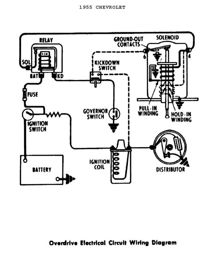
In some vehicles, such as older models or classic cars, the ignition coil may be externally mounted on the distributor, while in modern cars, it is often integrated into the engine’s ignition system. Regardless of the configuration, the ignition coil plays a vital role in the engine’s operation, providing the necessary spark to ignite the air-fuel mixture and power the vehicle.
How does an ignition coil work?
An ignition coil is a crucial component in the electrical system of an internal combustion engine. It plays a vital role in the ignition process, converting the low voltage from the battery into the high voltage needed to create a spark in the spark plugs.
The construction of an ignition coil consists of two main parts: a primary winding and a secondary winding. The primary winding consists of a few hundred turns of a thick, insulated copper wire, while the secondary winding consists of thousands of turns of a thin, insulated wire. These windings are wound around a core made of iron or magnetic material.
When the ignition switch is turned on, the battery sends a low voltage current to the primary winding of the ignition coil. This current creates a magnetic field around the primary winding which is then transferred to the core. As the current flow in the primary winding suddenly stops, the magnetic field collapses and induces a high voltage current in the secondary winding.
This high voltage current is then sent to the distributor, which distributes the voltage to the appropriate spark plug for each cylinder, where it ignites the fuel-air mixture. The ignition coil continuously repeats this process to ensure that each spark plug fires at the correct time, allowing for smooth engine operation.
In summary, an ignition coil works by converting the low voltage from the battery into a high voltage current needed to create a spark in the spark plugs. This process is achieved through the electromagnetic principles of the primary and secondary windings, along with the use of a core material to transfer and amplify the magnetic field.
Common Wiring Diagrams for GM Ignition Coils
In General Motors (GM) vehicles, the ignition coil plays a crucial role in the ignition system by converting the battery’s low voltage into high voltage needed to create a spark in the spark plugs. Understanding the wiring diagrams for GM ignition coils is important for troubleshooting and repairing ignition-related issues. Here are some common wiring diagrams for GM ignition coils:
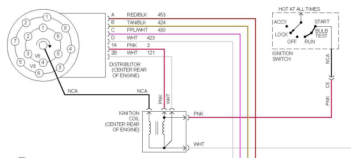
1. Single-Connector Ignition Coil Wiring Diagram:
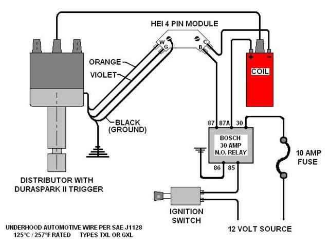
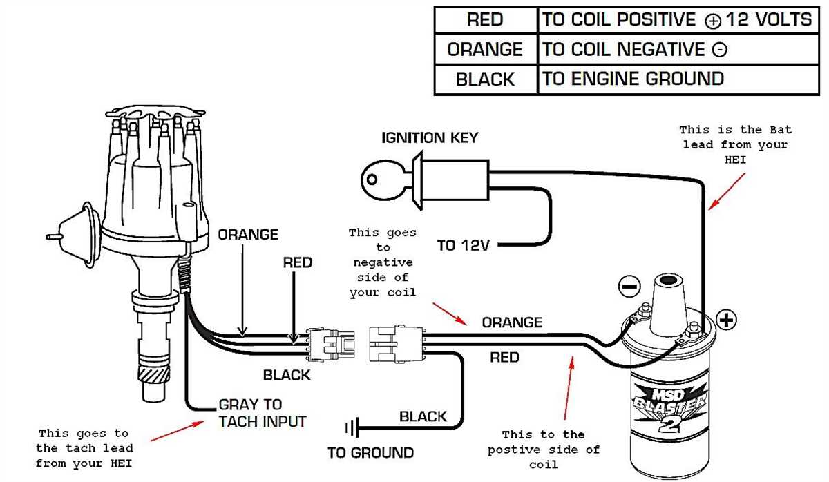
The single-connector ignition coil wiring diagram is used in older GM vehicles. This diagram shows a single ignition coil with a four-wire connector. The wires in the connector are color-coded as follows: the black wire is for the coil’s primary circuit, the red wire is for the battery positive terminal, the white wire is for the coil’s secondary circuit, and the yellow wire is for the ignition module’s control signal.
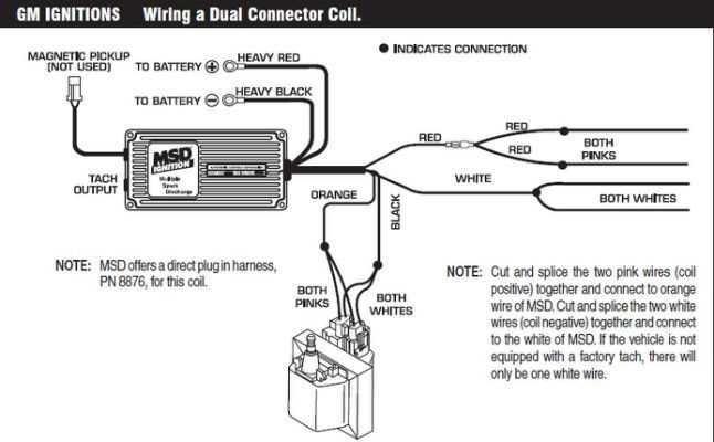
2. Dual-Connector Ignition Coil Wiring Diagram:
The dual-connector ignition coil wiring diagram is used in newer GM vehicles with individual ignition coils for each cylinder. This diagram shows two ignition coils, each with its own connector. The wires in the connectors are color-coded as follows: the orange wire is for the battery positive terminal, the black wire is for ground, the pink wire is for the coil’s primary circuit, and the white wire is for the coil’s secondary circuit.
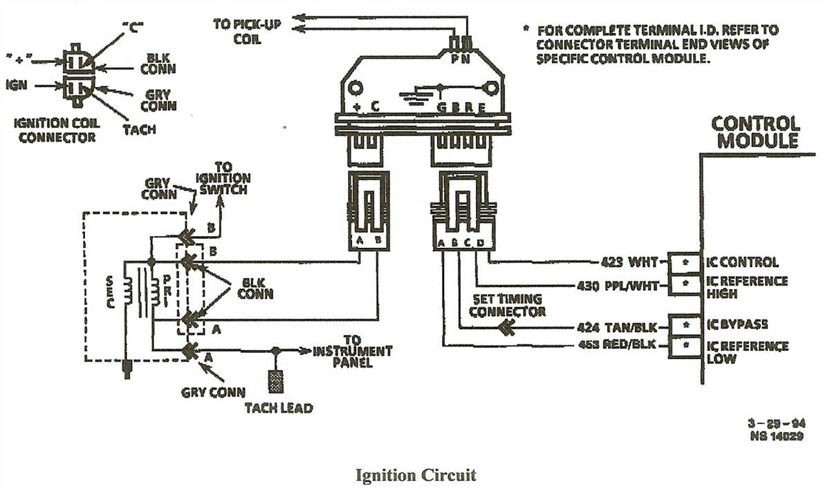
3. Coil-on-Plug Ignition Coil Wiring Diagram:
The coil-on-plug ignition coil wiring diagram is used in modern GM vehicles with a coil-on-plug ignition system. This diagram shows individual ignition coils mounted directly on each spark plug. The wires in the connectors are color-coded as follows: the orange wire is for the battery positive terminal, the black wire is for ground, the pink wire is for the coil’s primary circuit, and the white wire is for the coil’s secondary circuit.
Understanding and following these wiring diagrams for GM ignition coils can help technicians and automotive enthusiasts diagnose and repair ignition system issues effectively. It is always recommended to refer to the specific vehicle’s service manual for accurate and detailed wiring diagrams.
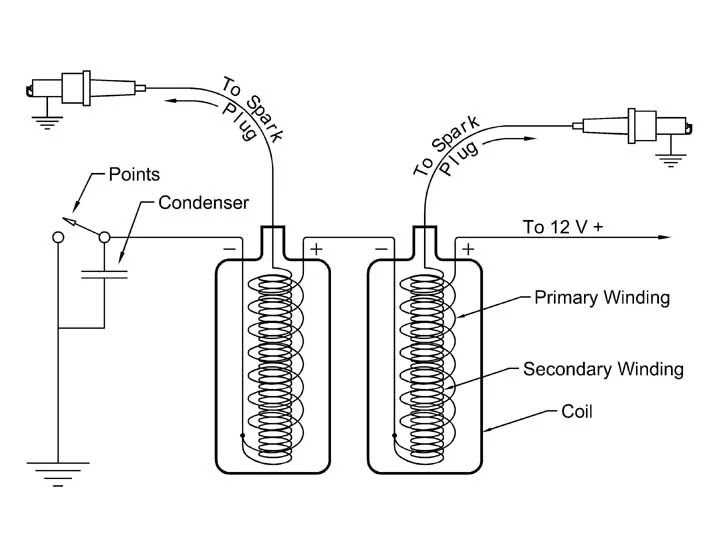
Wiring Diagram for Single Ignition Coil
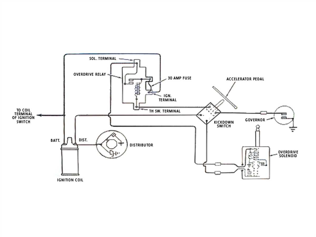
An ignition coil is a vital component of the ignition system in a vehicle, responsible for converting the battery’s low voltage into the high voltage needed to create a spark for the engine. The wiring diagram for a single ignition coil outlines the connections and electrical paths between various components involved in the ignition process.
Here is a step-by-step guide on how to wire a single ignition coil:
- First, locate the ignition coil in your vehicle. It is usually mounted on or near the engine, with a set of wires connected to it.
- Identify the primary and secondary terminals on the ignition coil. The primary terminal is usually marked with a (+) sign or a positive symbol, while the secondary terminal may be marked with a (-) sign or a negative symbol.
- Connect the positive terminal of the ignition coil to the ignition switch using a wire. This wire is responsible for supplying power to the coil from the battery.
- Connect the negative terminal of the ignition coil to the distributor cap or the spark plug wire using another wire. This connection is responsible for delivering the high voltage spark to the spark plugs.
- Make sure all connections are secure and properly insulated. Inspect the wires for any signs of damage or wear and replace them if necessary.
It’s important to note that the specific wiring diagram for a single ignition coil can vary depending on the make and model of the vehicle. Therefore, it is always recommended to refer to the vehicle’s manual or consult a professional mechanic for accurate and model-specific instructions.
Wiring Diagram for Multiple Ignition Coils
When it comes to the wiring diagram for multiple ignition coils, it’s essential to understand how each coil connects to the electrical system. Ignition coils are responsible for providing the high voltage necessary to ignite the fuel-air mixture in the combustion chamber of an internal combustion engine. Multiple ignition coils are commonly found in engines with multiple cylinders.
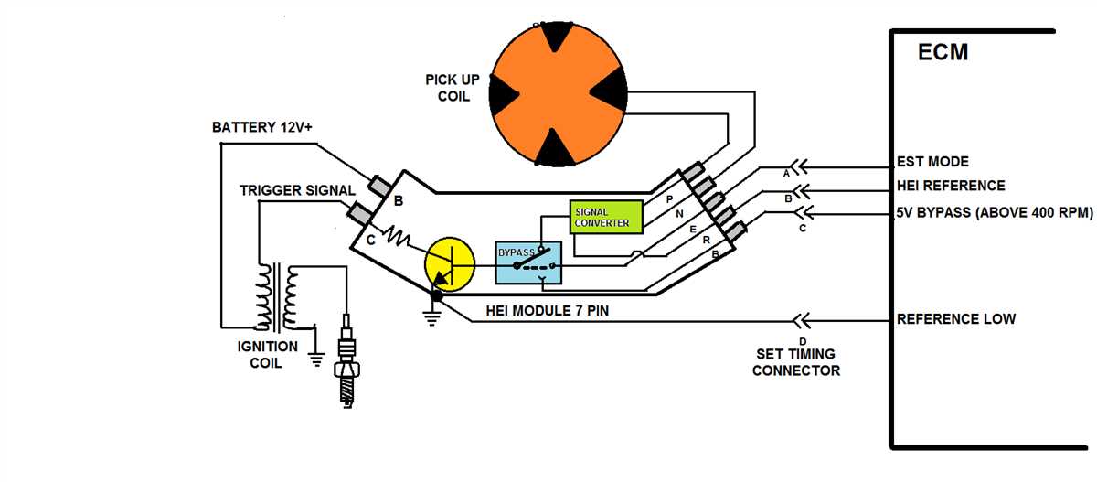
1. Distributorless Ignition System: In modern vehicles, most ignition systems have transitioned from a distributor-based system to a distributorless ignition system (DIS). In this system, each cylinder has its own ignition coil, which eliminates the need for a distributor. Each coil connects directly to the engine control module (ECM) or ignition control module (ICM).
2. Coil-on-Plug System: Another common configuration is the coil-on-plug (COP) system, where each cylinder has its own ignition coil located directly on top of the spark plug. This design allows for more precise ignition timing control and eliminates the need for spark plug wires. Each ignition coil in a COP system connects directly to the ECM or ICM.
- Coil 1: Connects to ECM pin A
- Coil 2: Connects to ECM pin B
- Coil 3: Connects to ECM pin C
- Coil 4: Connects to ECM pin D
- Coil 5: Connects to ECM pin E
- Coil 6: Connects to ECM pin F
It’s important to consult the vehicle’s wiring diagram or service manual to determine the specific wiring connections for the ignition coils in a particular vehicle model. Each manufacturer may have slightly different wiring configurations, so it’s crucial to follow the correct diagram to ensure proper functioning of the ignition system.
Troubleshooting Ignition Coil Wiring Issues
When it comes to troubleshooting ignition coil wiring issues in a GM vehicle, there are a few key steps to follow. By carefully examining the wiring diagram and systematically checking different components, you can identify any potential problems and rectify them efficiently. Here is a summary of the troubleshooting process:
- Inspect the wiring connections: Start by checking the wiring connections for any signs of damage or corrosion. Ensure that all connections are secure and properly grounded.
- Check the ignition coil for power: Using a multimeter, test for voltage at the ignition coil’s positive terminal. If there is no power, trace the wiring back to find the source of the issue, such as a blown fuse or faulty ignition switch.
- Verify the signal from the ignition module: Disconnect the coil wire from the ignition coil and connect a spark tester. Crank the engine and check for a consistent spark. If there is no spark, it may indicate a problem with the ignition module or crankshaft position sensor.
- Test the coil resistance: Measure the resistance of the ignition coil using a multimeter. Compare the readings to the manufacturer’s specifications. If the resistance is outside of the recommended range, the coil may need to be replaced.
- Inspect the coil packs (if applicable): If your GM vehicle has separate coil packs, inspect them for any signs of cracks, damage, or water intrusion. Faulty coil packs can cause misfires and other ignition issues.
- Ensure proper grounding: Check the grounding for the ignition coil and other related components. Loose or faulty grounding can disrupt the electrical flow and affect ignition performance.
In conclusion, troubleshooting ignition coil wiring issues in a GM vehicle involves careful examination of wiring connections, checking for power, verifying ignition module signals, testing coil resistance, inspecting coil packs, and ensuring proper grounding. By following these steps, you can identify and resolve any problems with your ignition coil wiring, allowing your vehicle’s ignition system to function optimally.