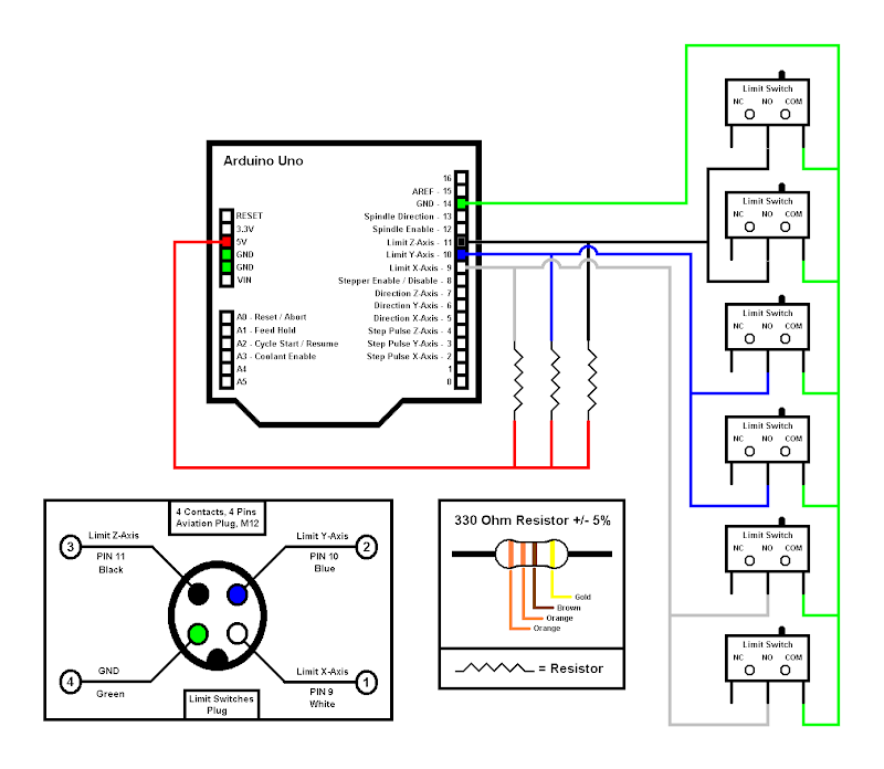
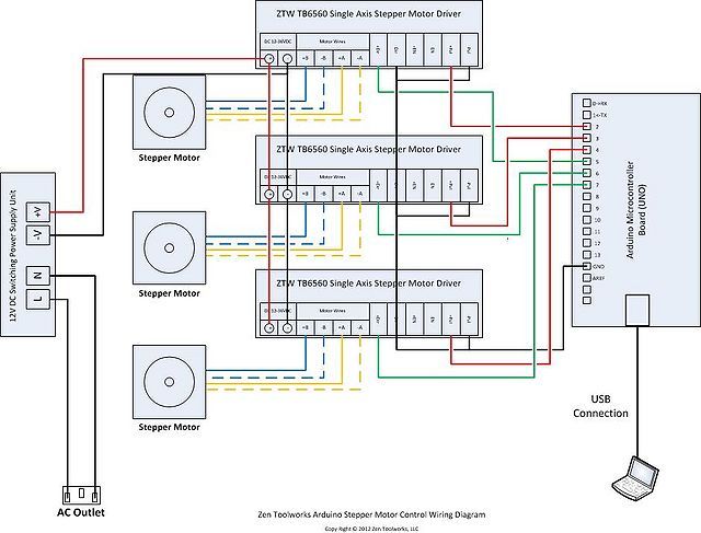
This instructable goes through the wiring procedure for using all of the same electronics as if you used an Arduino/RAMPS/GRBL/A (obviously not both.
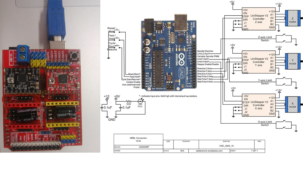
Pin diagram for Grbl v and v with the traditional layout: (NOTE: The wiring methods to minimize external electric noise on the input pins. We have given back to the GRBL project and developed a ARDUINO CNC SHIELD that is % GRBL compatible.(Click here for more details). The wiring is simple but there is no indication if one of the switches is The schematic of the end sensor board which uses optocouplers.
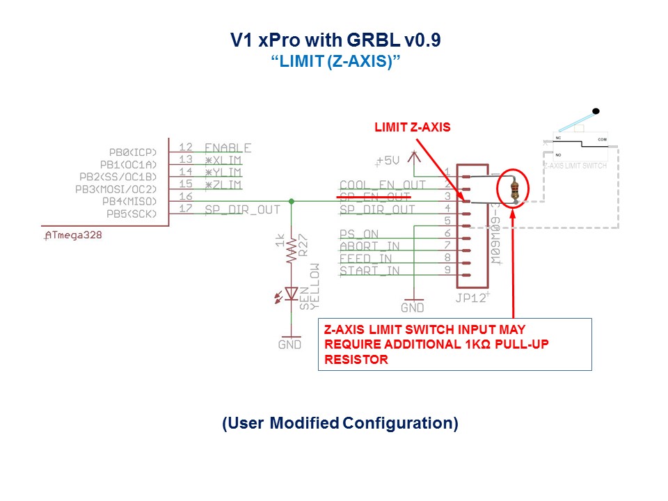
We have given back to the GRBL project and developed a ARDUINO CNC SHIELD that is % GRBL compatible.(Click here for more details).You see, now we are only declaring our variables. We are not assigning values to them, because we will be getting the values from the user. It is important, however, .
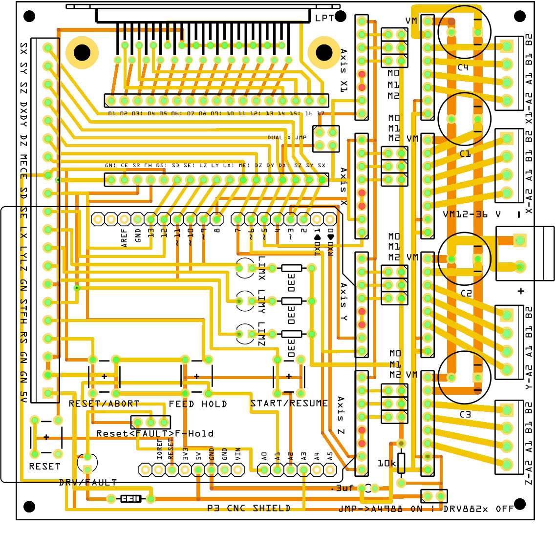
First, connect to Grbl using the serial terminal of your choice. Set the baud rate to as 8-N-1 (8-bits, no parity, and 1-stop bit.) Once connected you should get the Grbl-prompt, which looks like this: Grbl f [‘$’ for help] Type $ and press enter to have Grbl print a help message.
You. View and Download Pioneer VSXK service manual online. VSXK Receiver pdf manual download.
Also for: Vsxv-k, Vsxv-s, Vsxs. Find helpful customer reviews and review ratings for BIQU mw Violet Light DIY Double Motors Laser Engraving Machine High Engraving Speed Laser Engraver at schematron.org Read honest and unbiased product reviews from our users. The Quadstepper motor driver board allows you to control up to 4 bipolar stepper motors simultaneously using logic level IO pins.
Each motor driver has an output drive capacity of 35V and 1Amps.Probe connection – Upgrades – Inventables Community ForumPIONEER VSXK SERVICE MANUAL Pdf Download.