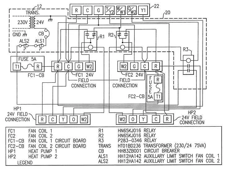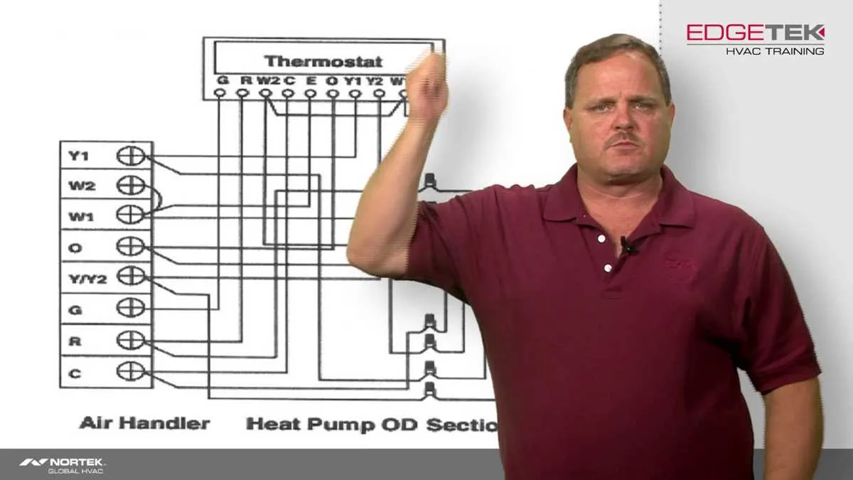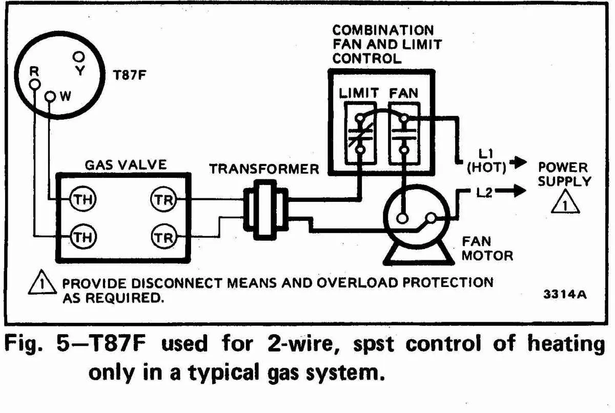
When working with residential or commercial temperature regulation units, ensuring the proper electrical setup is critical for optimal performance. A clear understanding of how each component connects can prevent malfunctions and ensure safety. Always start by verifying the correct voltage and current ratings for your specific model.
One of the most important steps is ensuring that the power supply is correctly routed to the main terminals. Incorrect connections can lead to excessive wear or even failure of the entire system. Focus on identifying the correct terminals for the power input, as well as the low and high-voltage connections.
Next, take special care with the reversing valve wiring. Incorrect configuration can cause issues with unit cycling, resulting in inefficient operation. Follow the manufacturer’s color-coding system to connect the wires to their designated terminals. If unsure, cross-reference with the manual to confirm the color-to-terminal mapping.
Finally, always verify ground connections and continuity. A weak or missing ground connection can lead to erratic behavior or even pose safety hazards. Additionally, using high-quality, insulated wires can minimize risk, particularly in areas with fluctuating electrical loads.
Electrical Connection Overview for Goodman System
Ensure proper wiring connections by following these specific guidelines for Goodman units:
- For 24V control circuit, connect the thermostat to the control board terminals. Common and R wires are essential for operational stability.
- For the compressor, connect the two larger wires (typically marked L1 and L2) to the appropriate terminals for efficient power transfer.
- Make sure the fan motor leads are correctly linked to the corresponding terminals to ensure balanced airflow.
- The defrost board should be wired directly to the compressor and reversing valve to guarantee proper cycle function.
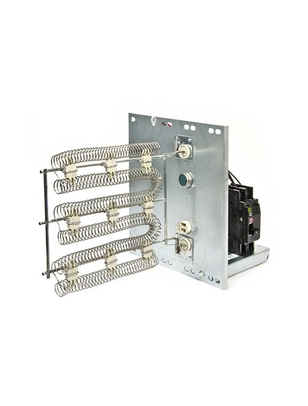
- Double-check the connection of the auxiliary heat strip, which should be powered separately through a dedicated relay.
For correct functionality, observe these essential voltage ratings:
- Ensure a 240V power supply for the main unit, with proper grounding and fuse protection to prevent overheating.
- Low-voltage control signals should always be routed through a secure, non-interfering path to avoid electrical issues.
- Check continuity before energizing the system to avoid short circuits and other electrical hazards.
Lastly, always refer to the manufacturer’s manual for specific wire gauge recommendations based on unit size and model to avoid potential damage or inefficiency.
Understanding Goodman Control Board Connections

For proper installation and troubleshooting, always refer to the control board’s terminal connections. Start by identifying the terminals clearly marked on the board. The most common connections include Y, C, R, and W. These correspond to the cooling, common, power, and heating components respectively.
Make sure that R is securely connected to the power input from the transformer. C should be connected to the common side, which helps complete the circuit. The Y terminal controls cooling, while W manages heating. These four are the core for standard operation. If a unit includes auxiliary features, you may encounter additional connections such as O for reversing valve control or B for backup heat.
Ensure all connections are clean and free from corrosion. Tighten all terminals properly to avoid any loose connections that could affect performance. If troubleshooting is necessary, check voltage at each terminal. A multimeter will help confirm that power is properly distributed across the board. Pay close attention to the O and B terminals, as wiring them incorrectly can result in inefficient system operation or failure to switch between modes.
For units with a defrost cycle, verify that the defrost sensor is wired to the correct input. The sensor ensures proper defrosting operation, and incorrect wiring could result in ice buildup or poor system performance.
Ensure to consult the manufacturer’s manual for specific board layouts and variations. Each model may have slight differences in control configurations.
Wiring the Reversing Valve in Goodman Heat Pumps

To correctly connect the reversing valve, ensure the correct terminals are used for each wire. The common terminal, usually labeled “C,” must be connected to the control circuit. For the reversing valve itself, the “O” terminal is typically assigned for cooling mode, and the “B” terminal is used for heating mode. Be sure to follow the manufacturer’s specifications to prevent malfunction or inefficiency in system operation.
For cooling mode: The “O” terminal receives a signal from the thermostat or control board, activating the valve to switch to cooling. Verify the system is set to cooling before proceeding with wiring.
For heating mode: The “B” terminal is energized, which inverts the valve’s operation to heat the environment. Ensure that all connections are clean and secure to prevent voltage drops.
Important tip: Double-check the voltage ratings before connecting. Incorrect voltage can damage components and impair functionality.
Using the proper gauge wire is crucial for efficiency and safety. Typically, 18 AWG wire is suitable for most connections, but always confirm based on the manufacturer’s guidelines.
Lastly, when performing the setup, inspect the valve and system for leaks or errors in operation before finalizing the installation.
Common Wiring Issues and Troubleshooting Tips

Ensure all connections are secure to avoid intermittent performance. Loose terminals often cause erratic operation or failure to start. Double-check all connections at the control board and compressor terminals, ensuring that no wires are frayed or improperly seated.
Overloaded circuits can cause tripping of fuses or circuit breakers. Verify that the system is on a dedicated circuit and confirm the fuse or breaker matches the recommended rating for the equipment. Replace any faulty components with appropriate replacements to restore proper function.
Incorrect voltage levels can lead to motor or compressor damage. Use a multimeter to confirm the voltage supplied matches the system’s specifications. Check for any signs of over-voltage or under-voltage conditions and ensure the power source is stable.
Contactor failure is a common issue, especially if the unit has not been maintained regularly. Inspect the contacts for any signs of wear, corrosion, or pitting. If the contacts appear damaged or dirty, replace the contactor to restore proper switching functionality.
Improper grounding can cause electrical malfunctions and safety hazards. Ensure that the system is properly grounded according to local electrical codes, as improper grounding can lead to electrical shocks or system failure.
Incorrectly wired reversing valves often result in failure to switch modes. If the system fails to alternate between cooling and heating, inspect the reversing valve terminals and ensure they are wired correctly according to the unit’s manual.
Check for short circuits or pinched wires inside the control box. This can be caused by poor insulation or improper routing. Look for any areas where wires may have rubbed against sharp edges, causing damage that could lead to a short.