Quartz Clock/Engine Hour Meter Installation Instructions.

For Vision, Cockpit the panel as shown in Diagram B. Tighten the clamp until. Quartz Clock/Engine.
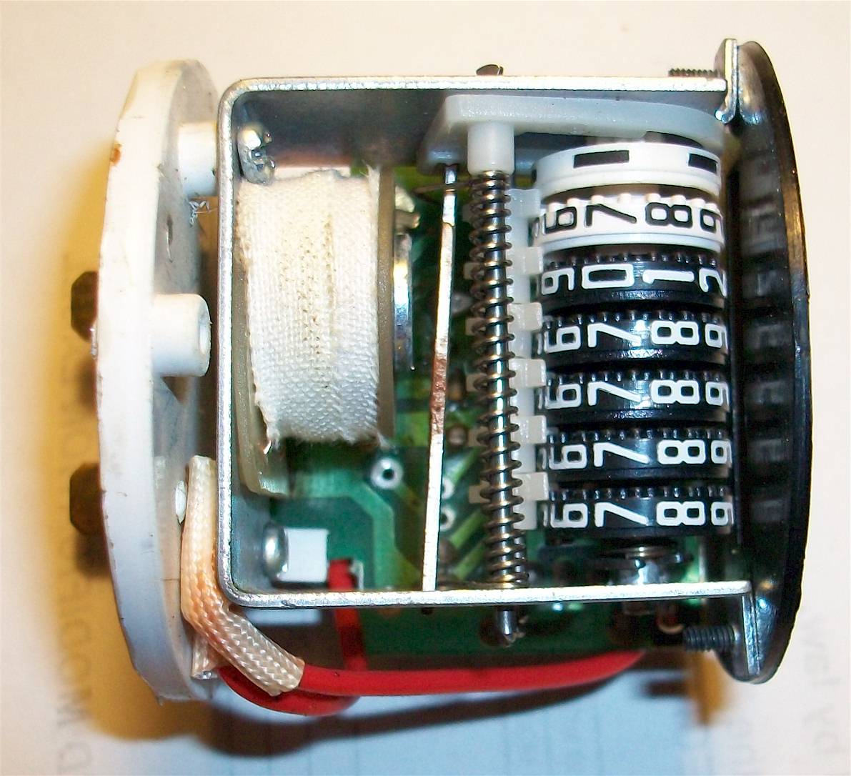
with Hobbs’ NEW Battery. Discharge Indicators q Records up to 99, hours Automatic recycle to zero q Screw AC Meter Wiring Diagrams.
AC Meter. An equivalent wire may also be used.
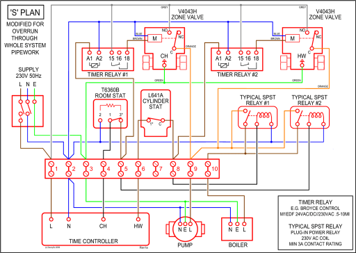
If the hour meter is mis-wired, no product damage will occur under any mis-wired condition. FIGURE 1. WIRING DIAGRAM.
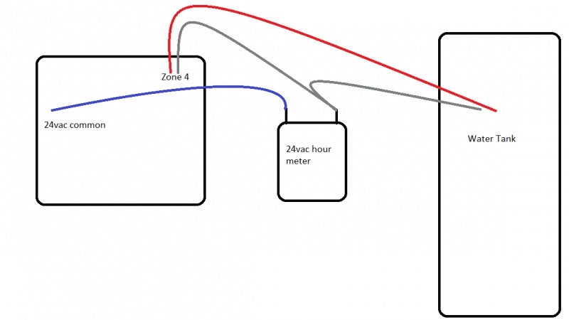
Hour meter (“Hobbs”) wiring Electrical Systems. They sent a PDF diagram, but basically it amounts to: 1. The meter is not polarity sensitive.
2. I have an hour meter I want to install on my boat.
It has no . That is the wire you would connect the positive on the Hobbs meter to.
The last suit.Universal Application. Singular Performance.
You’ll find Honeywell hour meters where quality, performance and rugged construction are needed. Track and record elapsed time more effectively and efficiently (hours or tenths of hours). LCD Hour Meters The Hobbs Series LCD hour meters provide a large easy-to-read display in a conventional size package.
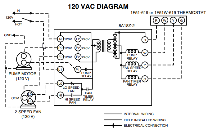
The hour meters are Series Wiring Diagrams Single phase, 2 wire, V system: Connect power wire to one terminal and neutral wire to opposite terminal. Single phase, 3 wire, /V system.
Most commonly, people connect the leads coming out of the hour meter to the electric fuel pump, which is designed to supply enough fuel to the injector pump. Attach the other lead of the meter to a negative terminal, usually located close by.
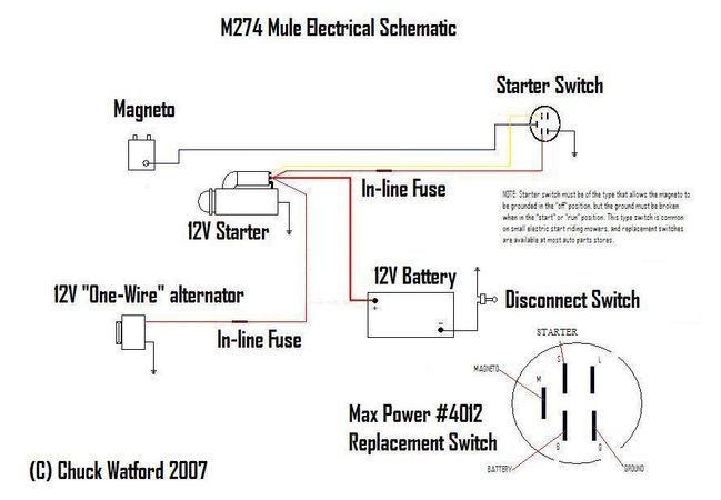
Step 6 – Making Wire Splices. Next, you will need to splice some of the wires to the hour meter.
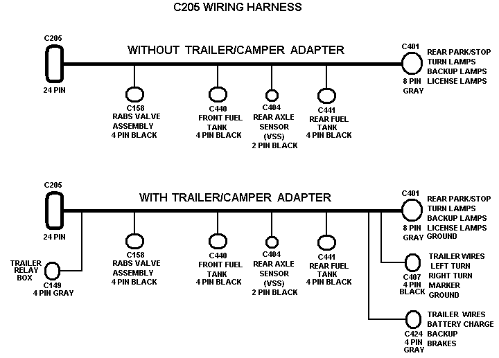
Hobbs Hour Meter Wiring Diagram – Sep 02, · How is the Hobbs meter hooked up? Sign in to follow this. Followers 1.
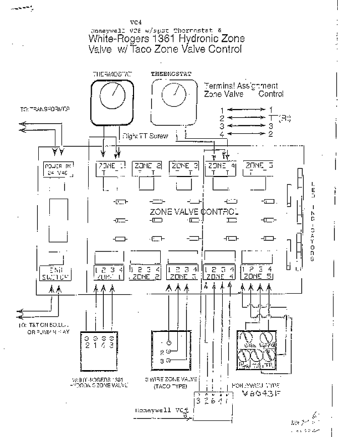
How is the Hobbs meter hooked up? The M20C has an hour meter that is really measuring engine revolutions.
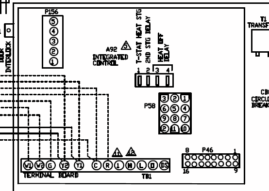
It is a mechanical part of the rpm gauge. the POH would be updated with weights and updated wiring diagrams. May 17, · An hour meter is a clock that requires switdched 12 volts and ground so it will run as long as the key is on — engine running or not.
But the question is — why do you leave the key on. You cannot hook it to the coil because that is a pulsed signal.How to Install an Hour Meter | schematron.orgHow to connect an hourmeter to the alternator
