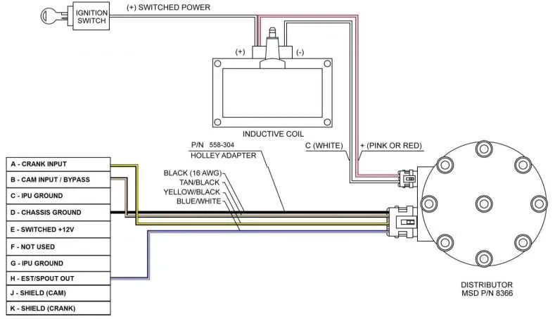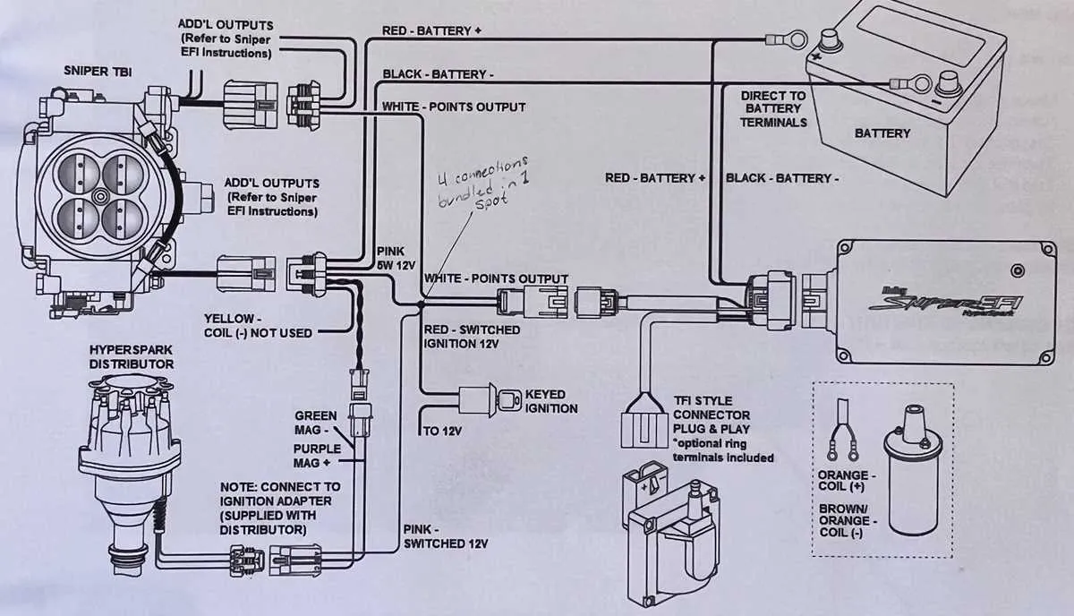
Ensure proper connection between your fuel management unit and vehicle’s electrical system by following the precise wiring layout. Start by identifying the main components: fuel delivery system, control unit, and sensors. Use the correct gauge wires to avoid overheating or failure due to current overload.
Refer to the power supply connections for the control unit. Typically, a dedicated 12V wire is necessary to power the system. Ensure a reliable ground connection to prevent any electrical interference. The use of a fuse is highly recommended to protect the system from power surges.
The fuel injectors require a stable signal for efficient operation. Use high-quality, insulated wires to connect these injectors to the control unit. Maintain short wire runs to minimize signal loss and improve response time.
When connecting sensors such as the throttle position or air temperature, always verify the pin configuration. Incorrect wiring can lead to poor engine performance or misreading of vital data. Double-check all connections before testing the system.
Finally, secure all cables properly, ensuring they are routed away from heat sources or moving parts to avoid wear and tear. Use zip ties or clamps to keep wires neatly organized and out of harm’s way.
Electrical Setup for Modern Fuel Injection Systems
Ensure precise connection of the fuel management system by following the pinout layout. Start by locating the main control unit and grounding it properly. A secure ground is vital for system stability.
Connect the power supply to the designated terminal, ensuring it matches the required voltage specifications. Use high-quality, insulated cables to avoid short circuits. The system’s main power wire should be routed directly to the battery for a consistent power source.
The injectors must be linked to their respective pins on the controller. Confirm the polarity and resistance values before attaching them. Incorrect connections can lead to performance issues.
Incorporate the fuel pump relay and connect it according to the recommended diagram for activation. The relay’s trigger wire must be linked to the proper signal from the control unit. Additionally, integrate the temperature and pressure sensors to the corresponding inputs.
Finally, verify all connections and test the system with a multimeter to check voltage and continuity. Regularly inspect wiring for wear, and replace any components showing signs of corrosion or damage.
Wiring the Fuel Management System for Initial Setup

Start by connecting the power supply to the system’s main harness. Ensure that the positive terminal is linked to a stable 12V source, and the ground wire is securely connected to a metal part of the chassis for proper grounding.
Next, route the fuel injectors’ leads to their respective locations. The injector wires should be connected to the corresponding pins on the main module, taking care not to mix up the polarity.
For the throttle position sensor, identify the signal, reference, and ground wires. Connect the signal wire to the appropriate input on the control unit, ensuring a reliable ground connection to the system’s common ground point.
The oxygen sensor must be installed and wired properly for accurate readings. Use the designated pins for the signal and heater control to ensure that the sensor operates within its optimal range.
Make sure to connect the fuel pump relay to the appropriate output, ensuring that the pump receives power when the ignition is turned on. This will ensure fuel is delivered properly during operation.
Double-check all connections before powering up the system. Use a multimeter to confirm the correct voltage levels at critical points. Incorrect wiring can lead to malfunction or failure of the system.
Once the setup is complete, verify that the system is receiving power and that all sensors are functioning by checking the control unit’s display or diagnostic outputs. This will help ensure that the system is ready for calibration.
Connecting Power and Ground Wires for the EFI System
For proper operation, the power and ground connections must be securely established. Start by routing the positive wire from the system to a reliable ignition-switched 12V power source. Use a fuse rated at 10-15 amps to protect the circuit. Ensure that the fuse is placed as close to the power source as possible to prevent overcurrent damage.
The ground wire should be connected to a clean, unpainted surface on the vehicle’s chassis or engine block. Avoid grounding to areas with paint, corrosion, or dirt, as this can cause poor connections and system malfunctions. Use a ring terminal and bolt to secure the wire to the chassis, ensuring a solid connection.
Inspect all connections regularly to ensure no corrosion or loose connections, which can lead to system failures. Proper grounding and power supply are critical for stable operation.
Troubleshooting Common Electrical Issues with Fuel Management Systems
If your system isn’t performing correctly, start by verifying all connections to the power supply. A loose or corroded connection can prevent the unit from receiving the correct voltage.
- Check the ground connection to ensure it’s securely attached to a clean metal surface.
- Ensure the main power wire is not damaged and properly connected to the battery or fuse panel.
If the fuel management system isn’t responding or showing errors, inspect the sensor wiring and connections.
- Verify the throttle position sensor, air intake sensor, and manifold absolute pressure (MAP) sensor connections.
- Look for any frayed or shorted wires that may cause inconsistent readings.
For fuel delivery issues, inspect the fuel pump wiring and relay connections. A faulty relay or broken wire could disrupt fuel supply.
- Test the relay using a multimeter to check for continuity.
- Confirm the power wire to the pump is not loose or corroded.
Lastly, check the fuse box for any blown fuses, as they can interrupt system functions. Replace any damaged fuses with the correct rating.
- Replace fuses immediately if they appear blown to avoid potential damage to the unit.
- Make sure the fuse box terminals are clean and free of rust.