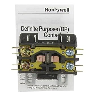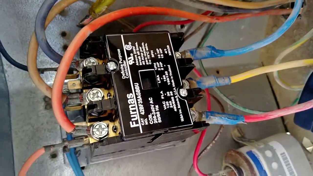
Air Conditioning and Cooling Systems – Honeywell Compressor Contactor I attempted wiring the new contactor in the following manner. Features.
Meets ARI Standard at started ratings (, cycle mechanical life, , cycle electrical life and 10, cycle recycle life); the most. installation to prevent electrical shock or equipment damage.
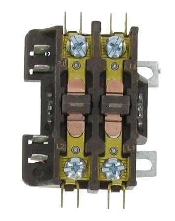
Location Disconnect power supply before beginning installation to prevent electrical Honeywell Limited-Honeywell Limitée. Gordon Baker Fig.
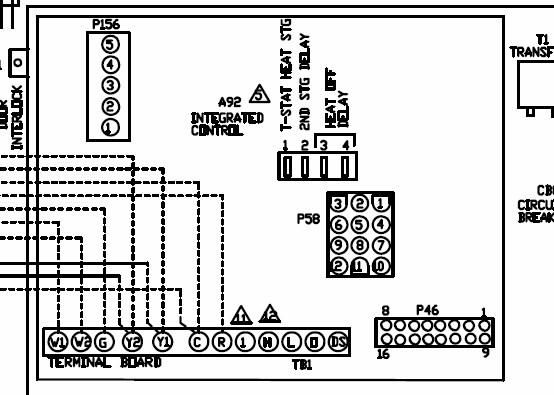
2. Typical wiring diagram.

installation to prevent electrical shock or equipment damage. Location Disconnect power supply before beginning installation to prevent electrical Honeywell Limited-Honeywell Limitée. Gordon Baker Fig.

2. Typical wiring diagram.
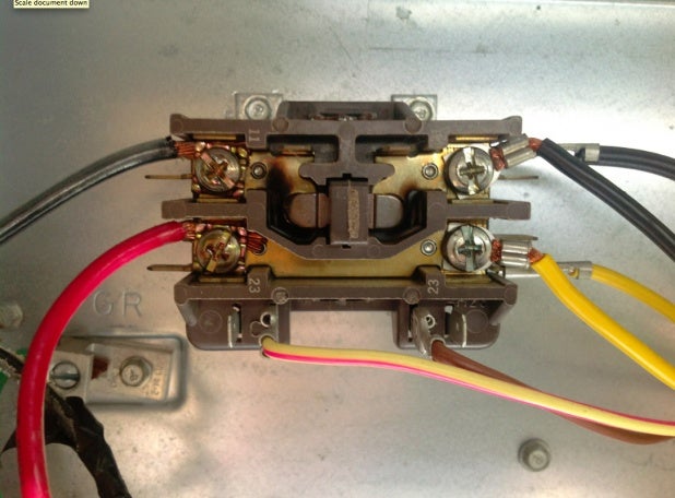
The 24V wire terminals on the OLD contactor were located on the TOP and have been Honeywell DPA Definite Purpose Contactor Only caveat I have to say is there needs to be a “Help Diagram” for those switching from the.Honeywell DPA Definite Purpose Contactor. Order on-line where the contractors buy and save. • Low profile design allows for more wiring room.
schematron.org is a division of On Time Mall Inc. and is not associated with Honeywell International Inc.
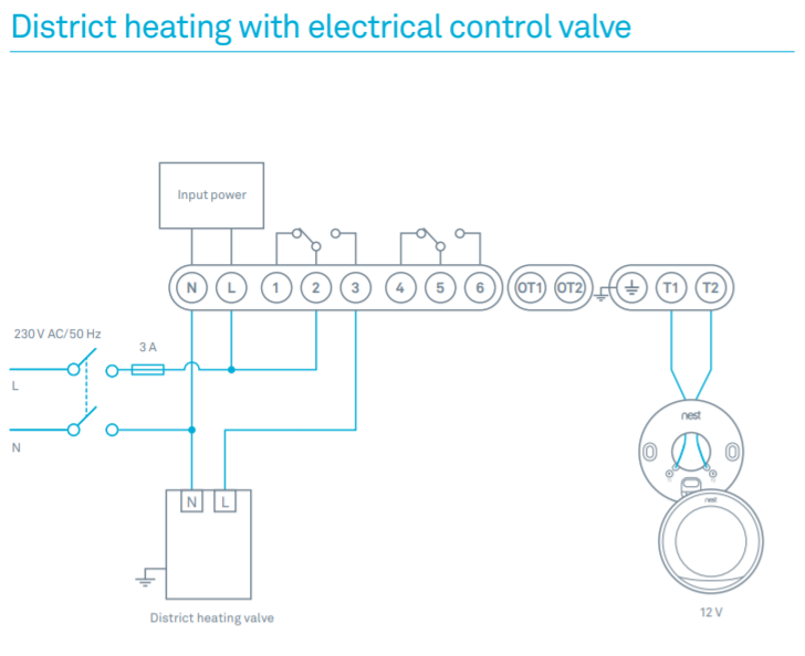
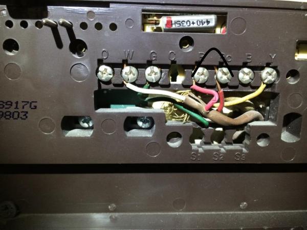
5 Wire Honeywell Thermostat Wiring. Some programmable thermostats (e.g. Honeywell Prestige wiring requirements) need a minimum of 5 wires, and maybe more depending on what features you want to operate (humidifier, etc).
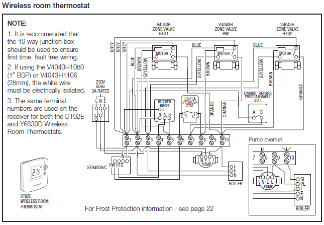
The additional 5th wire will be for common; providing stepped down power from a transformer. 7 ES—03 RTH/RTH Set jumper JP1, on the back of the thermostat, if you have connected a wire to the G terminal. 6 Set Heating Fan Control HG Leave the jumper in this factory-set position if you have a gas or oil furnace.
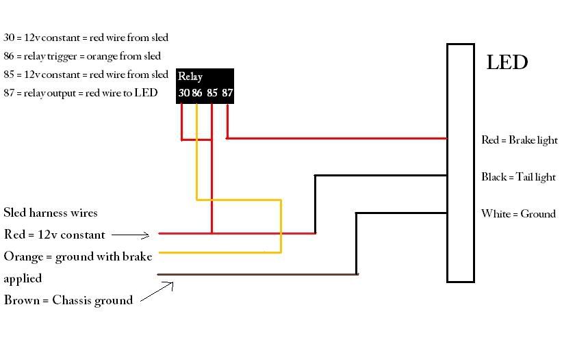
HE Place the jumper to . Honeywell Thermostat Wiring Diagram 4 Wire Examples The table above provides a more complete list of Honeywell thermostat wiring colors and their uses.
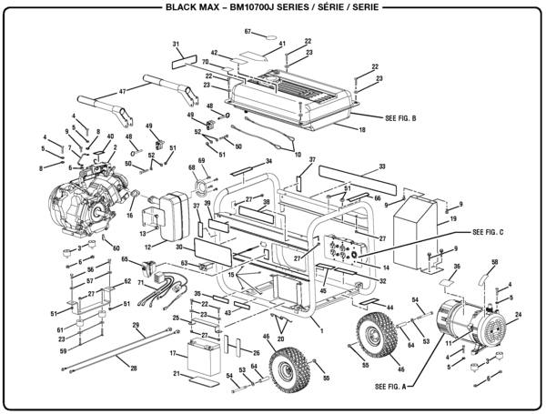
But here is a list of the most common wire color mappings, as seen in many four wire t-stat setups. I highly recommend this brand new DPA Honeywell Air Conditioner heat pump Contactor.

The DPA contactor is single pole, rated at 32 full load amps and has a 24 volt coil. I really like the Honeywell DPA contactor because it has large terminal screw connectors on both ends for easy wire installation.Honeywell Compressor Contactor Upgrade Problem – schematron.org Community ForumsHoneywell Thermostat Wiring Instructions | Diy House Help
