
If you are an avid model railway enthusiast, then you are likely familiar with Hornby’s range of turntables. These turntables are essential for easily changing the direction of your locomotives on your layout. However, many people struggle with the wiring aspect of the turntable, as it can be quite complex. In this article, we will provide you with a comprehensive wiring diagram for Hornby turntables, making it much simpler for you to set up and operate.
Firstly, it is important to understand the different components of the turntable. Hornby turntables consist of a deck, track segments, drive gear, and a control unit. The deck is where your trains will rest and can typically accommodate multiple locomotives. The track segments allow the trains to enter and exit the turntable, while the drive gear rotates the deck. Lastly, the control unit is responsible for operating the turntable and changing the direction of the locomotives.
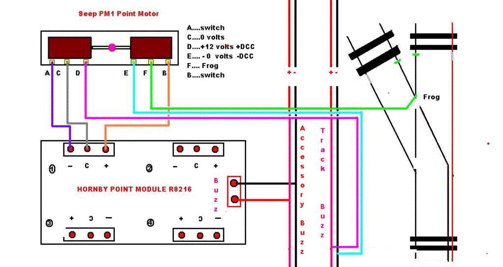
Now let’s move on to the wiring aspect of the turntable. To wire the turntable correctly, you will need to connect the control unit to the track segments using wires. The control unit will have designated terminals for each track segment. It is crucial to follow the wiring diagram accurately to ensure proper functionality. The diagram will indicate which wire should be connected to which terminal on the control unit, making it easier for you to set up the turntable without any guesswork.
Overall, understanding the wiring diagram for Hornby turntables is crucial for setting up and operating them efficiently. With the correct wiring, you’ll be able to control the direction of your locomotives effortlessly. If you are struggling with the wiring aspect, refer to the provided diagram, and you’ll be on your way to smooth operation in no time!
Hornby Turntable Wiring Diagram
When it comes to wiring a Hornby turntable, there are a few key components and connections that need to be considered. The wiring diagram provides a visual representation of how these elements should be connected to ensure proper operation of the turntable.
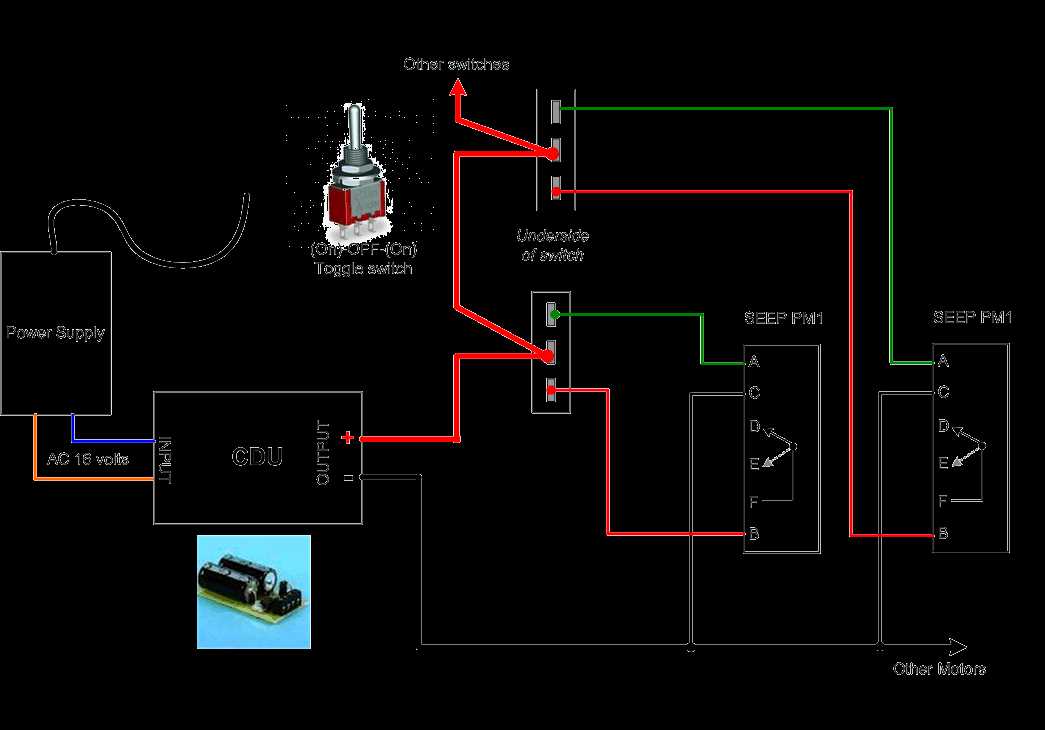
One important component of the wiring diagram is the power supply. The turntable requires a stable power source to operate effectively. This can be achieved by connecting the power supply to the designated terminals on the turntable motor, as indicated in the diagram. It is crucial to ensure that the power supply meets the necessary voltage and current requirements of the turntable.
Another essential aspect of the wiring diagram is the control panel. This is where the user can control the movement and position of the turntable. The diagram outlines how various control switches and buttons should be connected to the control panel. This allows the user to rotate the turntable in both directions and stop it at desired positions.
The wiring diagram also includes the connection points for the track and locomotives. These connections enable the turntable to function as a central point for trains to enter and exit the layout. The diagram specifies where the track and locomotive connections should be made to ensure seamless operation and smooth transitions between the turntable and the rest of the railway system.
By following the wiring diagram for the Hornby turntable, model railway enthusiasts can ensure that their turntable operates reliably and efficiently. It provides a clear and concise guide on how to connect the power supply, control panel, and track connections to maximize the functionality of the turntable within their railway layout.
Understanding the Hornby Turntable
The Hornby turntable is a popular model railway accessory used to rotate locomotives and rolling stock in a railway layout. It consists of a circular platform with tracks that can accommodate multiple tracks, allowing the user to position and rotate the trains as desired. Understanding the wiring diagram of the Hornby turntable is crucial to ensure proper functionality and integration with the rest of the layout.
Power Supply: The Hornby turntable requires a separate power supply to operate. It is important to connect the power supply to the turntable motor and control panel using the wiring connections specified in the wiring diagram. This ensures that the turntable can be controlled effectively and reliably.
Motor Control: The motor control is an essential part of the Hornby turntable. It allows the user to rotate the turntable clockwise and counterclockwise. The wiring diagram provides instructions on how to connect the motor control unit to the turntable motor, allowing for precise control of the rotation speed and direction.
Turntable Indexing: The turntable indexing feature enables the turntable to stop at specific positions, aligning the tracks with the approaches. This is achieved by connecting the indexing unit to the turntable motor and control panel according to the prescribed wiring connections. The wiring diagram outlines the necessary steps to configure and calibrate the indexing unit for accurate positioning.
Accessory Decoders: To enhance the functionality of the Hornby turntable, accessory decoders can be connected to control additional features such as turntable lights, sound effects, or even automatic train positioning. The wiring diagram provides instructions on how to connect and configure the accessory decoders to interface with the turntable and other track components.
By understanding and following the wiring diagram of the Hornby turntable, users can ensure proper installation and integration of the turntable into their railway layout. This allows for seamless control and operation, adding an interactive and realistic dimension to the overall model railway experience.
Components of the Hornby Turntable
The Hornby turntable is a key component in model railway layouts, allowing trains to change tracks and direction. It consists of various components that work together to facilitate the smooth operation of the turntable. Some of the main components include:
1. Turntable Deck
The turntable deck is the circular platform that holds the tracks and rotates to change the position of the train. It is typically made of sturdy plastic or metal and has a central pivot point for rotation. The deck is designed to fit different types of locomotives and rolling stock.
2. Turntable Motor
The turntable motor is responsible for rotating the deck. It is usually an electric motor that is connected to the turntable deck through gears or a belt. The motor can be controlled manually or through a digital command system, allowing precise positioning of the turntable.
3. Turntable Control Unit
The turntable control unit is a device that manages the operation of the turntable. It allows the user to control the speed and direction of the turntable motor, as well as control the positioning of the turntable deck. The control unit is often equipped with buttons or a joystick for easy operation.
4. Track Connectors
The track connectors are the points where the tracks on the turntable deck connect to the main railway tracks. These connectors ensure smooth transfer of trains from the turntable to the rest of the layout. They are usually equipped with electrical contacts to provide power and control signals to the trains.
These are just a few of the key components of the Hornby turntable. Each component plays a vital role in the proper functioning of the turntable, allowing model railway enthusiasts to create dynamic and realistic train movements on their layouts.
Step-by-Step Wiring Guide
To properly wire a Hornby turntable, follow these step-by-step instructions to ensure accurate and reliable operation. Each step provides clear guidance on the necessary connections and configurations.
1. Gather the Required Materials
Before starting the wiring process, gather the necessary materials. This may include a multimeter, soldering iron, solder, wire strippers, electrical tape, and specific Hornby turntable wiring components such as a controller, motor, and track connections.
2. Identify the Connecting Points
Identify the connecting points on the turntable, controller, and motor. This will include the power supply terminals, track connections, and any additional wires required for motor control.
3. Connect Power Supply
Start by connecting the power supply to the designated terminals on the controller or power distribution board. Ensure that the voltage matches the turntable’s requirements and follow any polarity indications.
4. Connect Track Connections
Next, connect the track connections to the turntable. Use solder or suitable connectors to make secure and reliable connections. Follow the Hornby turntable wiring diagram provided to determine the correct wire order and connections.
5. Wire the Motor
Wire the motor according to the wiring diagram provided with the turntable. This will typically involve connecting the motor wires to the designated motor control terminals on the controller or power distribution board.
6. Test the Wiring
Before finalizing the wiring, test the connections using a multimeter to ensure continuity and proper voltage levels. This step will help identify any potential wiring errors or faulty connections.
7. Secure and Insulate the Connections
Once the wiring is confirmed and tested, secure the connections using solder or suitable connectors. Additionally, insulate any exposed wires or connections using electrical tape or heat shrink tubing to prevent short circuits or damage.
Following this step-by-step wiring guide will ensure a well-connected and reliable Hornby turntable. By carefully following the wiring diagram and instructions, you can enjoy smooth and efficient operation of your turntable for years to come.
Troubleshooting Common Issues
When dealing with the wiring of a Hornby turntable, there are several common issues that may arise. By understanding these issues and knowing how to troubleshoot them, you can ensure that your turntable operates smoothly and efficiently.
One common issue is a lack of power to the turntable. If the turntable is not receiving power, first check that it is properly connected to a power source. Ensure that the power supply is turned on and that the power cable is securely plugged in. If the turntable still does not receive power, try using a different power outlet or power supply to rule out any potential issues with the original power source.
Another common issue is incorrect wiring connections. It is important to refer to the wiring diagram provided by Hornby when connecting the turntable to the power supply and controller. Check that each wire is properly connected to the correct terminal and that there are no loose or frayed connections. If necessary, consult the wiring diagram again and make any necessary corrections.
Additionally, mechanical issues can occur with the turntable. If you experience difficulty in turning or positioning the turntable, check for any obstructions or debris that may be preventing smooth movement. Clean the turntable and ensure that all moving parts are properly lubricated. If the issue persists, refer to the turntable’s instruction manual for further troubleshooting steps.
In summary, when troubleshooting common issues with the wiring of a Hornby turntable, first check for power supply issues, then inspect the wiring connections, and finally address any mechanical problems. By following these steps and referring to the appropriate resources, you can effectively troubleshoot and resolve any issues that may arise.
Advanced Wiring Techniques
In this section, we will explore some advanced wiring techniques for Hornby turntables. These techniques can help improve the functionality and reliability of your turntable setup.
1. Separating Power Sources
- One common issue with turntable setups is interference from other connected devices. To reduce this interference, consider using separate power sources for the turntable and other devices.
- By using separate power sources, you can isolate the electrical signals and minimize the chance of interference affecting the performance of the turntable.
2. Wiring for Multiple Tracks
- If you have a turntable with multiple tracks, you may need to wire them separately to avoid shorts or incorrect connections.
- Make sure to label the wires and keep a clear diagram of the wiring, so you can easily identify and troubleshoot any issues that may arise.
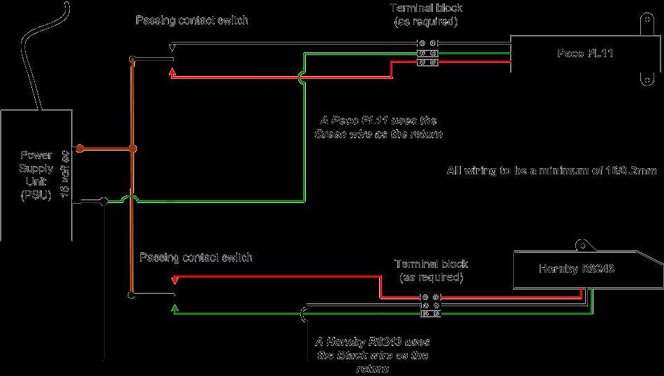
3. Using Terminal Blocks
- Terminal blocks can be used to simplify wiring and make it easier to connect and disconnect wires as needed.
- By using terminal blocks, you can create a central wiring point for your turntable setup, making it easier to manage and troubleshoot any issues.
Conclusion
By implementing these advanced wiring techniques, you can enhance the performance and reliability of your Hornby turntable setup. Separating power sources, wiring for multiple tracks, and using terminal blocks are just a few ways to improve your turntable’s functionality. Remember to always follow safety guidelines and consult the manufacturer’s instructions when making any wiring modifications.
Q&A:
What are advanced wiring techniques?
Advanced wiring techniques refer to the use of specialized methods and tools to accomplish complex electrical wiring tasks, such as circuit design, installation of high-capacity power lines, or routing wiring through tight spaces.
Why are advanced wiring techniques important?
Advanced wiring techniques allow for more efficient and reliable electrical installations. They can also help save space, reduce electrical interference, and improve overall safety and performance.
What are some common advanced wiring techniques?
Some common advanced wiring techniques include wire-bundling, wire-routing, soldering, use of specialized connectors or terminals, and implementing methods to mitigate electrical noise or interference.
Are there any risks associated with advanced wiring techniques?
Yes, there are potential risks when implementing advanced wiring techniques, such as electrical shock hazards, fire hazards, or damage to sensitive electrical components. It is important to follow safety guidelines and regulations when using these techniques.
How can I learn advanced wiring techniques?
You can learn advanced wiring techniques through specialized training programs or courses offered by vocational schools, community colleges, or electrical trade organizations. Additionally, there are online resources and tutorials available to learn at your own pace.
What are advanced wiring techniques?
Advanced wiring techniques refer to the use of advanced methods and tools to create electrical connections in a safe and efficient manner. These techniques go beyond basic wiring practices and often involve specialized knowledge and skills.