To ensure smooth operation of your lawn equipment, having a clear visual representation of its assembly is crucial. The detailed blueprint provides exact placement for every component, helping with troubleshooting and upkeep. If you’re experiencing difficulties with the cutting mechanism or power transmission, pinpointing the exact location of wear and tear is the first step in efficient repair.
Understanding the layout of each section is vital for identifying potential issues with the blade rotation, belt tension, or wheel alignment. Each element, from the spindle housing to the engine belt connections, is arranged to offer a smooth mowing experience. Start by examining the tensioners and the blade mounting system for signs of damage or looseness.
Important areas to inspect include the cutting deck attachment points and the linkage between the drive mechanism and wheels. These often wear out first due to consistent motion and pressure. A thorough review of the diagram can also help in selecting the correct replacement parts when necessary, ensuring you purchase exactly what’s needed.
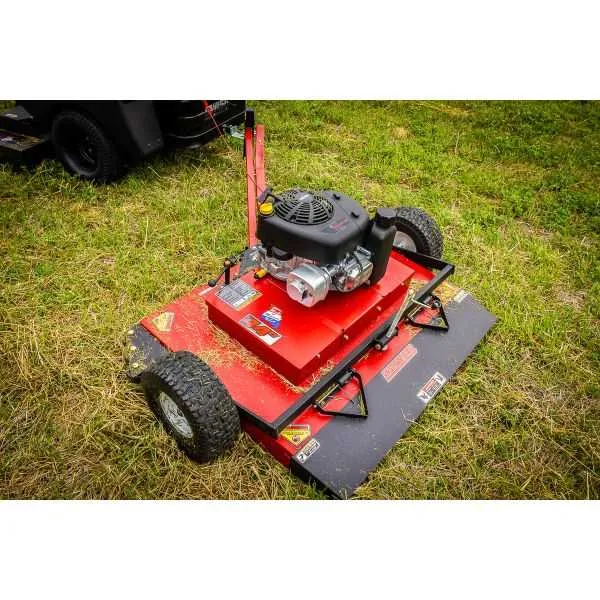
Maintenance Guide for 60-Inch Towing Lawn Equipment

For optimal performance, make sure to regularly inspect and maintain the key components of your 60-inch towable lawn cutting machine. Below are the crucial elements to check and maintain:
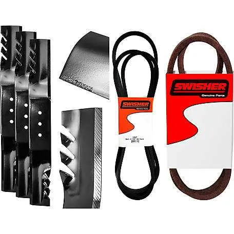
- Blades: Inspect for sharpness and wear. Replace if damaged or excessively worn.
- Deck: Ensure the cutting deck is free of debris and cracks. Clean after each use to avoid buildup.
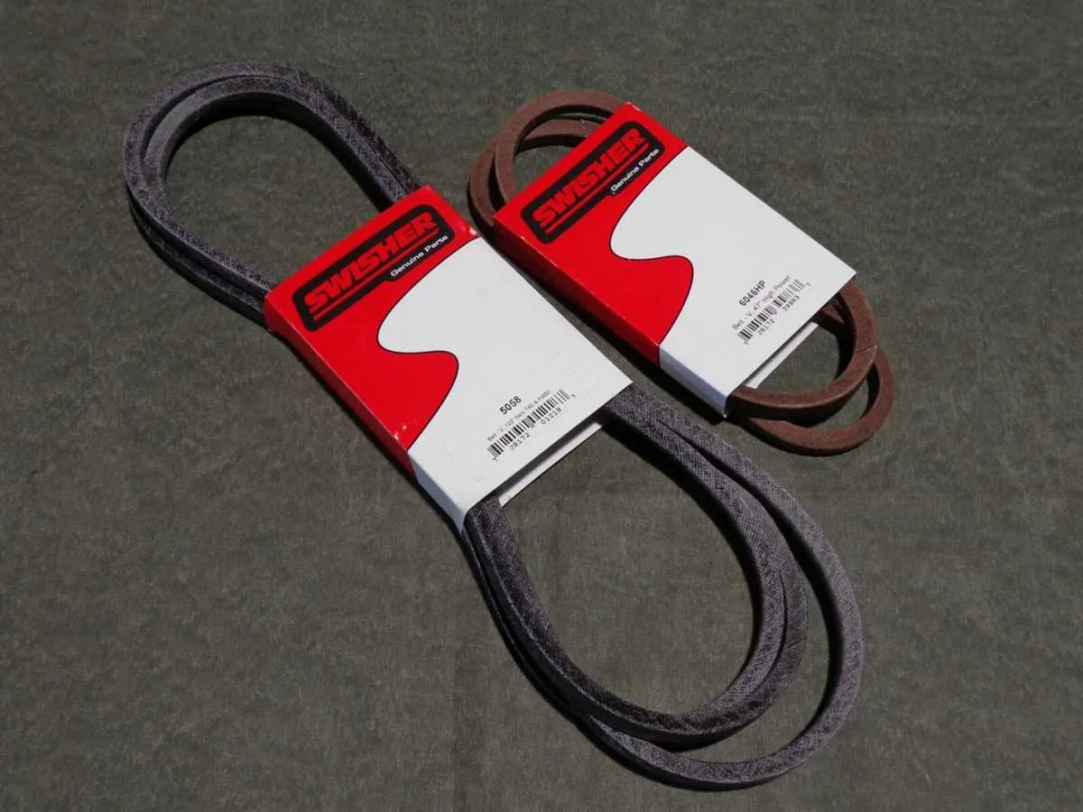
- Drive Belt: Check tension and condition. Replace if frayed or loose.
- Wheels: Examine wheel alignment and tire pressure. Adjust as needed for even cutting.
- Hitch Pin: Confirm that the hitch pin is securely fastened to prevent detachment during operation.
- Spindle: Lubricate regularly to ensure smooth rotation and prevent wear.
- Frame: Look for any bent or damaged parts. Repair or replace if necessary to maintain stability.
Additionally, using the correct lubricants and greases for each moving part is essential to extend the lifespan of your equipment. Refer to the user manual for recommended products and maintenance intervals.
Finally, ensure that all fasteners are properly tightened before use. Loose bolts can cause vibration and damage to the machine over time.
Identifying Key Components in the 60-Inch Lawn Care Equipment Layout

Focus on the main drive mechanism to ensure smooth operation. The engine assembly is essential for the functioning of the device, powering the cutting system. Check for any signs of wear or damage to the drive belt, as it plays a crucial role in transferring power. Replace it if any fraying or stretching is noticed.
The cutting blades are another critical component. They must be sharp and securely attached to ensure a clean cut. Regularly inspect the blade spindle for any looseness or damage, which could affect blade rotation. Tightening or replacing the spindle may be necessary for optimal performance.
Examine the deck assembly for signs of corrosion or wear. The deck houses the blades and provides structural support for cutting. Any issues with the adjustment mechanisms that control the height of the deck can lead to uneven cuts, so check these regularly to maintain consistency.
Inspect the transmission system for any irregularities that could affect the movement of the unit. Ensure that all gears and pulleys are properly aligned and free of debris. Faulty gears can result in a loss of power transfer, which directly impacts efficiency.
Don’t overlook the wheels and axles, which are vital for maneuverability. Ensure that the wheel bearings are in good condition and the axles are securely attached. Damaged bearings can cause dragging or improper movement of the equipment.
Finally, check the control mechanisms, including any levers or switches. These need to be responsive and in good condition to guarantee precise operation. Replace any worn-out components to avoid operational issues.
Troubleshooting Common Issues with the Assembly Breakdown

Check for engine power loss: If the machine is not starting or running smoothly, verify the fuel supply by inspecting the fuel lines. Ensure the fuel filter isn’t clogged, and that fuel is reaching the engine. Examine the ignition system for damaged wires or a faulty spark plug.
Inspect the cutting mechanism: If the blades are not engaging, check the belt tension. A loose or broken belt can prevent proper operation. Look for any obstructions around the spindle or blades, as debris could cause interference.
Clogged discharge chute: If grass is not properly exiting, examine the chute for clogs or blockages. Clean out any material buildup and check that the chute is securely attached to prevent air or material leaks.
Wheel alignment: Misalignment or uneven wheel height can result in uneven cuts. Ensure all wheels are properly adjusted to the correct height as per the manufacturer’s specifications. Use the visual reference in the assembly breakdown to confirm proper alignment.
Overheating engine: If the engine runs hot, inspect the cooling system for debris or blockages around the vents and air intake. Make sure the cooling fins are clear and that the oil level is within the recommended range.
Hydraulic system issues: In case of poor steering or erratic movement, check the hydraulic fluid levels. Low or contaminated fluid can affect performance. If necessary, replace the hydraulic fluid and inspect the seals for leaks.
Step-by-Step Guide to Replacing Components on the Swisher 60

Start by ensuring the unit is off and disconnected from any power sources. Use a jack to lift the machine and secure it with blocks for stability.
Next, inspect the blade assembly. Loosen the retaining bolts using a socket wrench and carefully remove the blade. Replace it with a new one, making sure the sharp edges face downward. Tighten the bolts securely.
For the belt replacement, first locate the tensioner and relieve the tension. Remove the old belt and install the new one, following the exact routing pattern indicated in the manual.
To replace the tires, lift the frame using a jack. Unscrew the tire bolts and replace with new wheels of the correct size. Ensure that the wheel nuts are tightened properly to avoid issues while operating.
Check the bearings in the axle and ensure they are greased. If damaged, use a bearing puller to remove them and replace with new ones. Always use the correct type of grease specified in the manual.
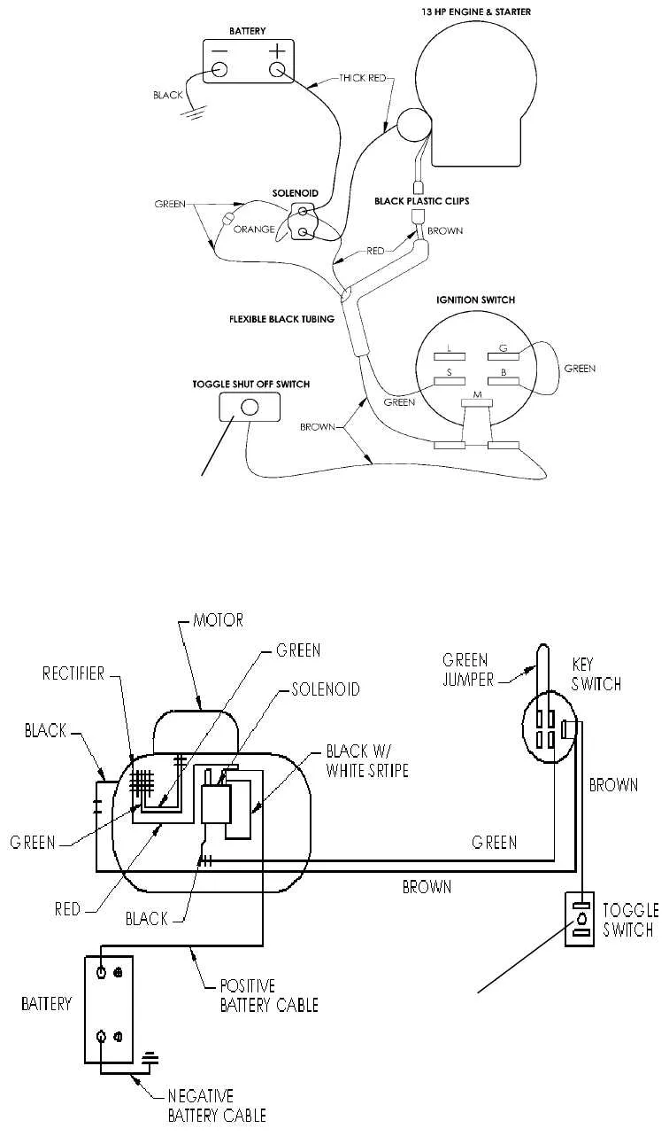
Lastly, inspect the wiring for any frayed or damaged sections. Repair or replace the wires as necessary. Make sure all connections are secure before testing the unit.