
The HVAC control wiring diagram is an essential component of any heating, ventilation, and air conditioning (HVAC) system. It provides a visual representation of the electrical connections and wiring that are used to control the various components of the system. This diagram is crucial for HVAC technicians and installers to understand how the system is connected and ensure that it is functioning properly.
The diagram typically includes symbols and labels that represent the different components of the HVAC system, such as thermostats, relays, switches, motors, and sensors. It shows how these components are interconnected and how they are controlled by the system’s control panel or thermostat. By following the wiring diagram, technicians can easily troubleshoot issues, identify faulty connections, and make necessary repairs or replacements.
Furthermore, the control wiring diagram is also beneficial during the installation process. It serves as a guide for technicians to correctly wire the system and ensure that all connections are secure and properly insulated. This diagram helps prevent potential hazards, such as short circuits or electrical fires, by providing clear instructions on how to connect the wires and components safely.
In conclusion, the HVAC control wiring diagram is a crucial tool for HVAC technicians and installers. It provides a visual representation of the system’s electrical connections and aids in troubleshooting, repairs, and installation. By understanding and following the diagram, professionals can ensure that the HVAC system functions efficiently and safely.
HVAC Control Wiring Diagram
In an HVAC system, control wiring is essential for the proper functioning of the various components. A control wiring diagram is a visual representation of the electrical connections and interconnections between the components of an HVAC system. It provides a detailed overview of how different parts of the system are connected to each other and to the control panel.
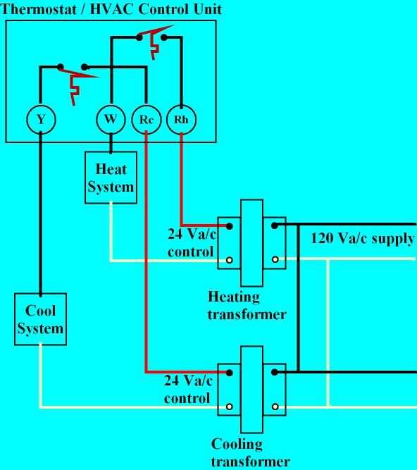
One of the key components in the control wiring diagram is the thermostat. The thermostat is responsible for sensing the temperature in a space and sending signals to the HVAC system to either heat or cool the area. It is connected to the control panel through low-voltage wiring, which allows for communication between the thermostat and other components of the system.
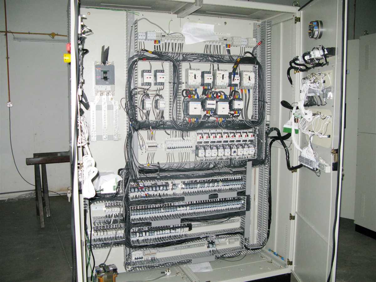
In addition to the thermostat, the control wiring diagram also includes other important components such as relays, contactors, and transformers. These components work together to control the flow of electrical power to different parts of the HVAC system. The control panel acts as the central hub that receives signals from the thermostat and sends commands to the various components to perform specific functions.
The control wiring diagram is an essential tool for HVAC technicians and electricians. It helps them understand how different parts of the system are connected and troubleshoot any issues that may arise. By following the wiring diagram, they can identify faulty connections, improper wiring, or malfunctioning components and take the necessary steps to rectify them.
In conclusion, a control wiring diagram is a crucial element in an HVAC system, as it provides a visual representation of the electrical connections and interconnections between the components. It helps technicians and electricians understand how the system functions and enables them to diagnose and resolve any issues efficiently.
What is HVAC Control Wiring Diagram?
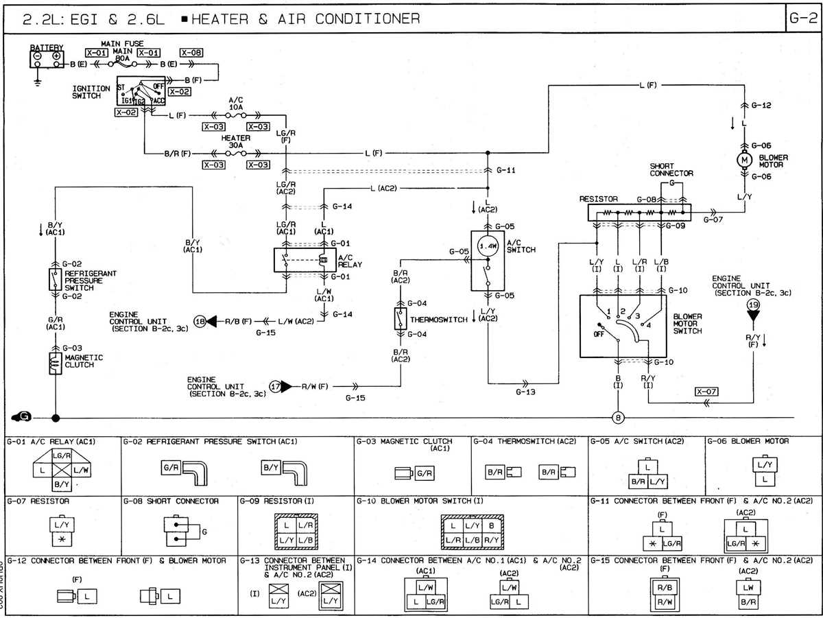
An HVAC control wiring diagram is a visual representation of the electrical connections and components within an HVAC system. It shows how different devices, such as thermostats, switches, motors, and relays, are connected to control the heating, ventilation, and air conditioning functions of the system.
The diagram is typically used by HVAC technicians and electricians to understand and troubleshoot the electrical circuitry of an HVAC system. It provides a detailed overview of how power is distributed and controlled, allowing for efficient operation and proper functioning of the system.
In an HVAC control wiring diagram, different symbols are used to represent various components and connections. For example, a thermostat may be represented by a rectangle with temperature settings, while a motor could be depicted as a circle with an “M” inside. Arrows and lines are used to indicate the flow of electricity and control signals between different components.
By studying the wiring diagram, technicians can identify potential issues, such as faulty connections, short circuits, or malfunctioning components, and take appropriate corrective actions. It also helps in understanding the sequence of operations and the logical flow of signals within the system.
In conclusion, an HVAC control wiring diagram is a valuable tool for understanding and troubleshooting the electrical aspects of an HVAC system. It provides a visual representation of the wiring connections and components, allowing technicians to ensure proper functioning and efficient operation of the system.
Components of HVAC Control Wiring Diagram
In an HVAC control wiring diagram, several components play a crucial role in controlling the heating, ventilation, and air conditioning system. These components work together to ensure the efficient operation of the HVAC system.
Here are some key components commonly found in HVAC control wiring diagrams:
- Thermostat: The thermostat is the primary control device in the HVAC system. It allows users to set the desired temperature and activates the appropriate heating or cooling equipment based on the temperature readings.
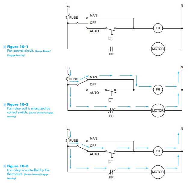
- Fan Relay: The fan relay controls the operation of the blower fan. It receives signals from the thermostat and activates the fan when the heating or cooling system is running.
- Transformer: The transformer in the control wiring diagram steps down the incoming voltage to a lower voltage suitable for the control circuit. It powers various control components, such as relays and contactors.
- Relays: Relays are electromechanical switching devices that control the operation of various components in the HVAC system. They receive signals from the thermostat and activate or deactivate the heating, cooling, and fan equipment as necessary.
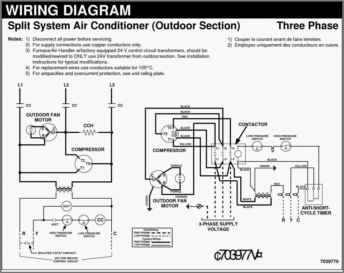
- Contactors: Contactors are used to control high-voltage equipment, such as compressors and outdoor fan motors. They receive signals from the relays and switch the power supply to the equipment on or off.
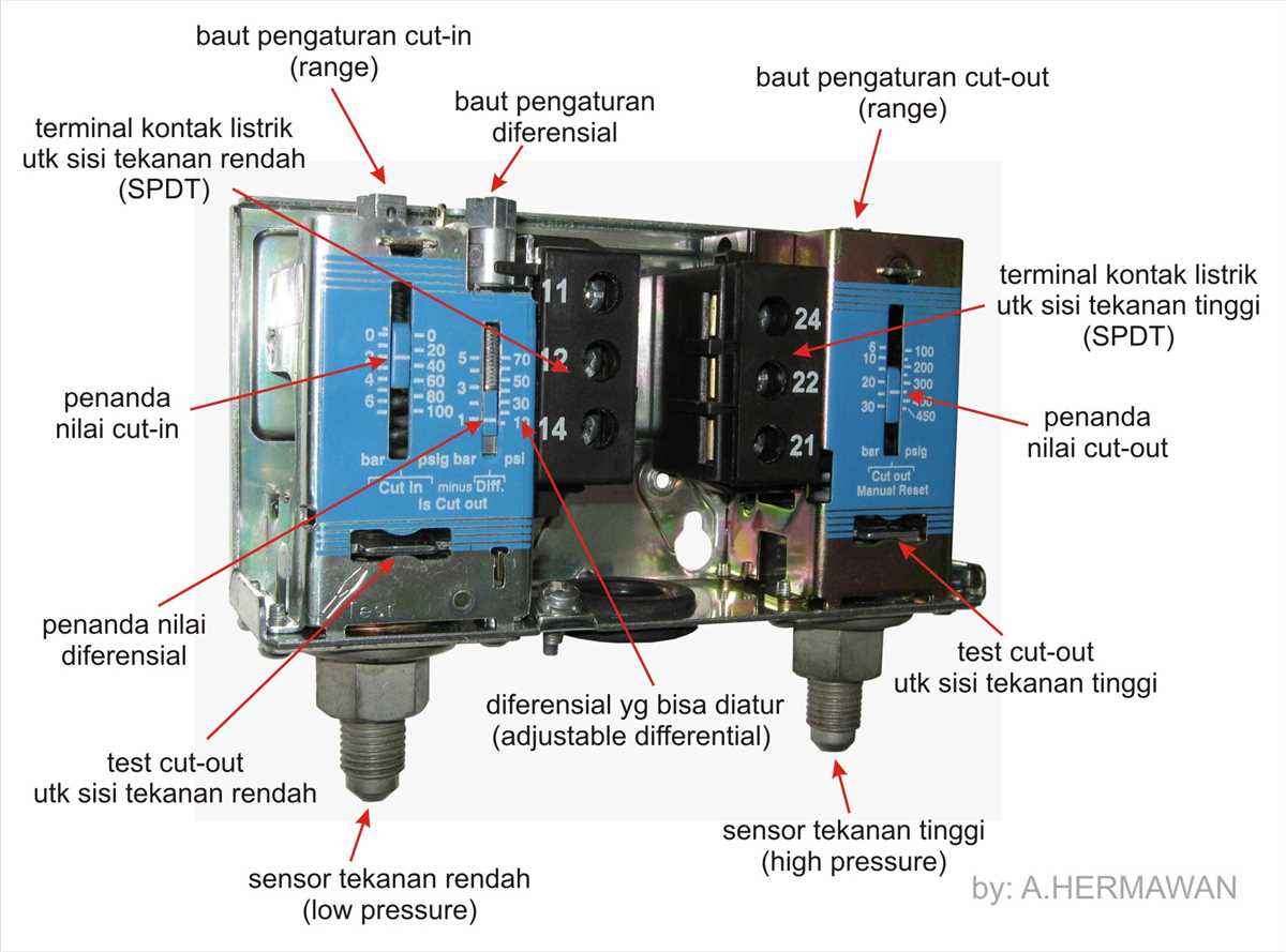
- Sensors: Sensors are devices that measure temperature, humidity, pressure, or other relevant parameters in the HVAC system. They provide input to the control circuit, allowing the system to make adjustments based on these readings.
In addition to these main components, HVAC control wiring diagrams may also include other devices, such as time delays, sequencers, limit switches, and other safety devices, depending on the specific system requirements. The wiring diagram provides a visual representation of how these components are connected and interact to control the HVAC system’s operation.
How to Read HVAC Control Wiring Diagram
Understanding the control wiring diagram is crucial for anyone working with HVAC systems. This diagram provides a visual representation of the electrical connections and components involved in controlling the heating, ventilation, and air conditioning (HVAC) system. By reading the control wiring diagram, technicians can diagnose and troubleshoot any issues with the system.
When reading an HVAC control wiring diagram, it is important to familiarize yourself with the symbols used in the diagram. These symbols represent various electrical components such as relays, switches, transformers, and motors. Each symbol has a specific meaning, and understanding these symbols is essential for interpreting the diagram correctly.
The diagram also shows the electrical connections between the different components. It indicates how power is distributed and how the control signals are transmitted. By analyzing the wiring diagram, technicians can determine the sequence of operation and how the various components interact with each other.
Another important aspect of reading an HVAC control wiring diagram is identifying the different control circuits. Control circuits are used to regulate the operation of the HVAC system, such as turning on or off the compressor, activating fans, or opening and closing dampers. Understanding the control circuits is crucial for troubleshooting any issues with the system.
Overall, reading an HVAC control wiring diagram requires a good understanding of electrical principles and the ability to interpret symbols and diagrams. It is a valuable skill for HVAC technicians and allows them to effectively diagnose and repair HVAC systems.
Common Wiring Diagram Symbols for HVAC Control
In HVAC control wiring diagrams, certain symbols are commonly used to represent various components and connections. These symbols help technicians and engineers understand how different parts of the HVAC system are interconnected and how they function.
1. Thermostat: The thermostat symbol is typically represented by a small box with a curved line inside, representing the temperature setting. It is used to control the operation of the HVAC system and set the desired temperature.
2. Relay: The relay symbol is represented by a square with an arrow pointing out of it. Relays are electromagnetic switches used to control larger electrical loads. They act as an intermediary between the thermostat and the HVAC equipment.
3. Transformer: The transformer symbol is usually represented by two diagonal lines with a dot in the middle. Transformers are used to step up or step down the voltage in an HVAC system, allowing the equipment to operate at the correct voltage level.
4. Motor: The motor symbol is typically represented by a circle with the letter “M” inside. It represents an electric motor used in HVAC equipment such as fans and compressors.
5. Capacitor: The capacitor symbol is represented by two parallel plates with a curved line between them. Capacitors store electrical energy and are used in HVAC systems to provide a power boost to start motors or to stabilize voltage fluctuations.
6. Switch: The switch symbol is represented by a line with an open or closed circle at one end. Switches are used to control the flow of electricity in an HVAC system, allowing the technician or user to manually turn equipment on or off.
7. Fuse: The fuse symbol is represented by a rectangle with a line through it. Fuses are safety devices that protect against electrical overload. They are designed to melt and break the circuit if the current exceeds a certain level, preventing damage to the equipment.
8. Resistor: The resistor symbol is represented by a zigzag line. Resistors are used to limit the flow of current in an HVAC circuit, ensuring that the electrical components operate within their specified limits.
These are just a few examples of the common wiring diagram symbols used in HVAC control systems. Familiarizing yourself with these symbols can help you understand and troubleshoot HVAC systems more effectively.
Step-by-Step Guide to Wiring HVAC Control System
Wiring an HVAC control system can seem daunting at first, but with a step-by-step approach, it can be a manageable and rewarding task. This guide will walk you through the process to ensure a successful installation of your HVAC control wiring system.
Step 1: Planning and Safety
Before you begin any wiring work, it is crucial to plan your system layout and ensure that you are familiar with the wiring diagram for your specific HVAC control system. Additionally, make sure to turn off the power to the equipment you will be working with to prevent any electrical accidents.
Step 2: Gathering Tools and Materials
Collect all the necessary tools and materials needed for the wiring job. This may include wire cutters, wire strippers, electrical tape, wire nuts, and the appropriate gauge wires for your system.
Step 3: Route the Wires
Carefully route the wires from the HVAC control panel to their respective devices, such as thermostats, dampers, and sensors. It is important to keep the wires organized and labeled for easy troubleshooting and maintenance in the future.
Step 4: Connect the Wires
Refer to the wiring diagram and connect the wires according to the specified connections. This typically involves connecting the corresponding color-coded wires together using wire nuts or terminal blocks.
Step 5: Test the System

Once all the wires are connected, it is essential to test the system to ensure it is functioning correctly. Test each component individually, including thermostats, sensors, dampers, and any other devices, to verify that they are responding appropriately.
Step 6: Secure and Label the Wiring
After confirming that the system is working correctly, secure the wiring in place using cable ties or clips. Additionally, label each wire and device to simplify future troubleshooting and maintenance tasks.
Step 7: Double-Check and Inspect
Before closing up the HVAC control panel, double-check all connections and wiring to ensure everything is properly secured and insulated. Inspect the system for any signs of loose wires or damaged components that may need immediate attention.
Step 8: Power On and Final Testing
Finally, turn on the power to the HVAC control system and conduct a final comprehensive test to confirm that all devices and components are functioning correctly. Monitor the system’s performance for the next few hours or days to ensure its stability.
By following this step-by-step guide, you can successfully wire an HVAC control system. Remember to prioritize safety, carefully follow the wiring diagram, and test the system thoroughly before considering the job complete. If you are unsure about any aspect of the process, consult a professional electrician or HVAC technician for guidance.