
A hydraulic press is a machine tool that uses hydraulic cylinders to generate a compressive force. It is commonly used in industries such as manufacturing, construction, and automotive to perform various tasks such as pressing, bending, straightening, and forming. The hydraulic press schematic is a representation of the different components and their arrangement in a hydraulic press.
The main components of a hydraulic press include the hydraulic cylinders, hydraulic pump, valves, and control unit. The hydraulic cylinders are used to generate the force by converting hydraulic energy into mechanical energy. The hydraulic pump is responsible for supplying the hydraulic fluid to the cylinders. The valves are used to control the flow and direction of the hydraulic fluid, while the control unit is used to monitor and regulate the operation of the hydraulic press.
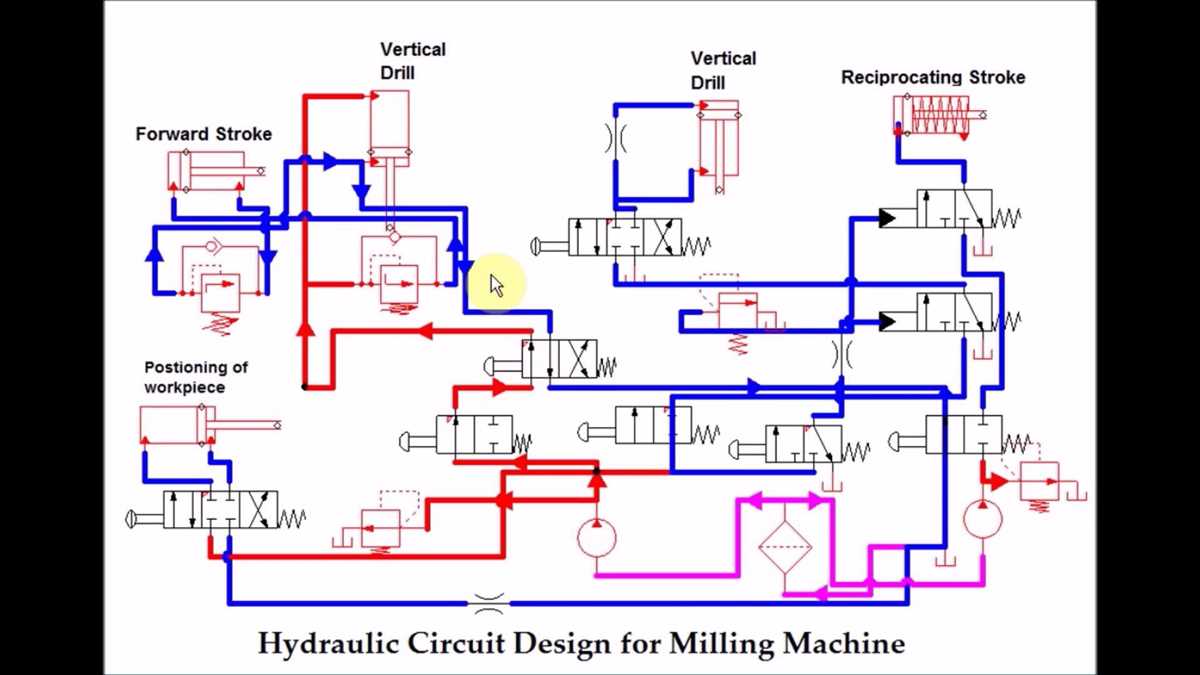
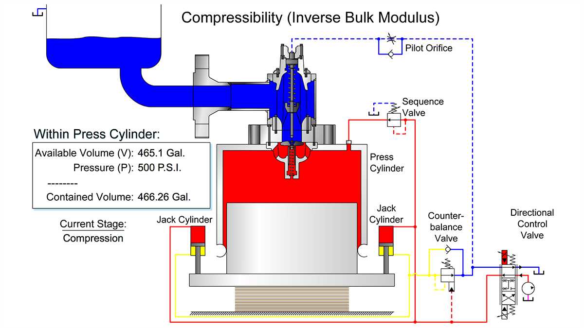
The hydraulic press schematic shows the flow of hydraulic fluid from the pump to the cylinders and back to the reservoir. It also illustrates the different valves and their positions for various operations and the control unit for regulating the pressure and force applied. Understanding the hydraulic press schematic is essential for operating and maintaining the hydraulic press effectively and safely.
In conclusion, the hydraulic press schematic provides a visual representation of the different components and their arrangement in a hydraulic press. It helps in understanding the flow of hydraulic fluid, the control of pressure and force applied, and the overall operation of the hydraulic press. With this knowledge, operators can effectively and safely use the hydraulic press for various tasks in different industries.
What is a Hydraulic Press?
A hydraulic press is a type of machine that uses hydraulic force to compress or shape materials. It is commonly used in industries such as manufacturing, construction, automotive, and aerospace. The press consists of a hydraulic system, a frame, and a ram. The hydraulic system generates and controls the force, while the frame provides support and stability. The ram, also known as the plunger or piston, is the moving part of the press that applies the force to the material.
The hydraulic press works based on Pascal’s law, which states that when pressure is applied to a fluid in an enclosed space, the pressure is transmitted equally in all directions. In the case of a hydraulic press, the fluid is typically oil or water. When a force is applied to the small piston, it creates pressure in the fluid, which is transmitted to the larger piston. This amplifies the force, allowing the press to exert a much larger force than the input force applied to the small piston.
Hydraulic presses are versatile machines that can be used for a wide range of applications. They are commonly used for metal forming and shaping processes such as forging, stamping, bending, and deep drawing. They can also be used for material testing, pressing powdered materials into solid shapes, compacting waste materials, and extracting oils from seeds. The precise control of force and speed makes hydraulic presses suitable for applications that require high accuracy and repeatable results.
Working Principle of Hydraulic Press
Hydraulic presses are powerful machines that utilize the principle of Pascal’s law to generate high pressure and apply it to a wide range of operations. The working principle of a hydraulic press involves the use of hydraulic cylinders and hydraulic fluid to produce force.
At the heart of a hydraulic press is the hydraulic cylinder, which consists of a piston and a cylinder that are interconnected. When hydraulic fluid is pumped into one side of the cylinder, it pushes the piston, creating a force. This force is then transferred to the object being pressed, exerting immense pressure.
The hydraulic fluid plays a crucial role in the working of a hydraulic press. It is usually oil-based and is stored in a reservoir. When the hydraulic pump is activated, it draws the fluid from the reservoir and pushes it into the cylinder. The pressure generated by the pump is transmitted to the hydraulic fluid, which then transfers it to the piston, resulting in the generation of force.
In addition to the hydraulic cylinder and hydraulic fluid, a hydraulic press also incorporates various other components such as valves, pipes, and control systems. These components work together to control the flow of hydraulic fluid and ensure precise and efficient operation.
The working principle of a hydraulic press enables it to exert immense force, making it suitable for a variety of applications. From metal forming and forging to stamping and compression molding, hydraulic presses are widely used in industries such as automotive, aerospace, and manufacturing.
Main Components of a Hydraulic Press
A hydraulic press is a powerful machine used to exert pressure on objects using fluid power. It consists of several main components that work together to generate and control the hydraulic force.
1. Hydraulic Cylinder:
The hydraulic cylinder is a crucial component of the hydraulic press. It contains a piston that moves linearly inside a cylindrical chamber. When hydraulic fluid is pumped into one side of the cylinder, it pushes the piston, creating force and movement. The hydraulic cylinder is responsible for generating the pressure required to perform the pressing action.
2. Hydraulic Pump:
The hydraulic pump is the heart of the hydraulic press. It is responsible for converting mechanical power into hydraulic power by pressurizing the hydraulic fluid. The pump draws in fluid from a reservoir, pressurizes it, and directs it to the hydraulic cylinder. There are various types of hydraulic pumps, including gear pumps, vane pumps, and piston pumps.
3. Control Valves:
Control valves are used to control the flow and pressure of the hydraulic fluid in the hydraulic press system. They direct the flow of fluid to different parts of the system and regulate the amount of pressure applied. Control valves allow for precise control and adjustment of the pressing force, speed, and direction.
4. Press Frame:
The press frame provides the structure and support for the other components of the hydraulic press. It is designed to withstand the forces exerted during the pressing operation. The frame is typically made of sturdy materials like steel and is rigidly constructed to ensure stability and safety.
5. Pressure Gauge:
The pressure gauge is an essential component for monitoring and measuring the pressure exerted by the hydraulic press. It helps operators ensure that the desired pressure is applied, preventing overloading or damage to the press or the processed objects. The pressure gauge is typically located in a visible position for easy reading.
- Overall, these main components work together to create a powerful and efficient hydraulic press capable of exerting tremendous force on objects.
- Without the hydraulic cylinder, the press would not be able to generate the necessary force for pressing.
- The hydraulic pump is responsible for supplying the pressurized fluid to the cylinder.
- The control valves enable precise control of the fluid flow and pressure, allowing for adjustment of the pressing force and speed.
- The press frame provides the structural support and stability needed during the pressing operation.
- The pressure gauge ensures that the correct pressure is applied, ensuring safe and efficient operation.
Hydraulic System
The hydraulic system is an essential component of a hydraulic press, as well as many other industrial and mobile machinery. It is a complex system that utilizes fluid pressure to generate force and transmit power. The key components of a hydraulic system include a reservoir, pump, valves, actuators, and fluid. This system is widely used in various industries due to its ability to provide precise and powerful force.
At the heart of the hydraulic system is the hydraulic pump, which is responsible for generating the required pressure by converting mechanical energy into hydraulic energy. The pump sucks in hydraulic fluid from the reservoir and pressurizes it, creating a flow of fluid through the system. This pressurized fluid is then directed towards the hydraulic actuators, such as cylinders or motors, which convert the hydraulic energy back into mechanical energy to perform the desired task.
The valves in the hydraulic system play a crucial role in controlling the flow and direction of the hydraulic fluid. They act as the switch that allows or blocks the fluid flow to different actuators or sections of the system. The valves can be manually operated or automated, depending on the application requirements.
The hydraulic fluid used in the system is usually a specially formulated oil with high viscosity and excellent lubricating properties. This fluid transfers power, lubricates the components, and helps to dissipate heat generated during the operation. It is important to regularly maintain and monitor the fluid level and cleanliness to ensure the proper functioning of the hydraulic system.
In conclusion, the hydraulic system is a vital component of a hydraulic press, providing the force necessary for its operation. With its ability to generate high forces with precision and control, the hydraulic system is widely used in various industries for a wide range of applications.
Control Unit
The control unit of a hydraulic press is responsible for managing and controlling the operation of the press. It is an essential component that ensures the press functions correctly and safely. The control unit consists of various components and systems, all working together to control the press’s movement, pressure, and speed.
Hydraulic Power Unit (HPU): The hydraulic power unit provides the necessary hydraulic power to the press. It typically includes a pump, motor, reservoir, and other components. The HPU is responsible for generating and maintaining the required pressure to operate the press.
Pressure Control System: The pressure control system regulates the hydraulic pressure within the press. It uses sensors and valves to monitor and adjust the pressure based on the desired settings. The pressure control system ensures that the press operates within safe limits and can handle the required load.
Speed Control System: The speed control system manages the speed at which the press’s components move. It uses valves and feedback mechanisms to control the flow of hydraulic fluid, thereby controlling the speed of the press’s movements. The speed control system allows for precise and controlled movements during various press operations.
Control Panel: The control panel is the interface between the operator and the press’s control unit. It typically includes buttons, switches, and indicators that allow the operator to start, stop, and adjust the press’s operation. The control panel also displays important information such as pressure, speed, and any error or warning messages.
Safety Systems: The control unit of a hydraulic press also includes various safety systems to ensure safe operation. These may include emergency stop buttons, safety interlocks, pressure relief valves, and overload protection mechanisms. These safety systems are designed to protect both the operator and the press from potential accidents or damages.
In summary, the control unit of a hydraulic press is a critical component that manages and controls the press’s operation. It includes systems for power generation, pressure control, speed control, and safety. The control panel serves as the interface between the operator and the control unit, allowing for easy operation and monitoring of the press’s performance.
Platen
The platen is an essential component of a hydraulic press schematic. It is a flat, rectangular plate made of a sturdy material such as steel or iron. The platen serves as the main surface that comes into contact with the material being pressed. It provides the necessary force and support for the hydraulic press to effectively apply pressure and shape the material.
Typically, the platen is attached to the hydraulic ram or cylinder, which is responsible for generating the force needed for pressing. When the hydraulic cylinder is activated, it pushes the platen downward, exerting pressure on the material placed on it. This pressure can be adjusted according to the specific requirements of the pressing process.
The platen is designed to distribute the pressure evenly across its surface, ensuring uniform compression and molding of the material. It is often equipped with various features such as heating elements or cooling channels to facilitate specific processes such as molding or curing. Additionally, the platen may have a textured or patterned surface to enhance grip and prevent slippage during the pressing operation.
Cylinder
The cylinder is a crucial component in a hydraulic press schematic. It plays a vital role in converting hydraulic energy into mechanical energy, allowing the press to generate the required force for various applications.
The cylinder consists of a cylindrical barrel and a piston that moves back and forth inside it. The barrel is typically made of a sturdy material like steel to withstand high pressures. The piston, on the other hand, is often made of a sealable material, such as rubber or plastic, to ensure a tight fit with the barrel walls.
When hydraulic fluid is pumped into the cylinder, it applies pressure on the piston, causing it to move. This movement exerts force on the objects placed on the press bed, allowing for a wide range of operations like bending, shaping, or pressing. The size of the cylinder and the diameter of the piston determine the force that can be generated by the hydraulic press.
It is essential to ensure that the cylinder has proper seals and is well-maintained to prevent leaks and ensure optimal performance. Regular inspections, lubrication, and replacement of worn-out parts are necessary to keep the cylinder in good working condition.
In summary, the cylinder is a critical component in a hydraulic press schematic that converts hydraulic energy into mechanical energy. Its design and functionality determine the force that can be generated by the press, making it an essential part of various industrial and manufacturing processes.
Conclusion
The ram is a crucial component in a hydraulic press, serving as the main force generator. It is responsible for applying pressure to the fluid in the cylinder, which in turn creates the force necessary to perform various tasks. The design of the ram is essential to ensure proper functionality and efficiency of the hydraulic press.
Throughout this article, we have discussed the various aspects of the ram in a hydraulic press. We started by understanding its basic function and the components that make up the ram assembly. We then delved into the different types of rams and their applications, including single-acting and double-acting rams.
We also explored the importance of choosing the right size and capacity of the ram for a hydraulic press, as well as the materials used in its construction. The proper maintenance and troubleshooting of the ram were also highlighted to ensure its longevity and optimal performance.
In conclusion, the ram is an integral part of a hydraulic press, playing a vital role in generating the necessary force for various industrial applications. Understanding its design, function, and maintenance is crucial for the successful operation of a hydraulic press.