
LED light bars have become popular accessories for off-road vehicles such as trucks, Jeeps, and ATVs. These powerful and efficient lights provide increased visibility and safety when driving at night or in low light conditions. One crucial component of an LED light bar setup is the switch that controls the lights. Understanding the switch diagram is essential for proper installation and operation of the LED light bar system.
The switch diagram of an LED light bar typically includes several key components. These include the switch itself, a fuse for protection against electrical overload, an on/off indicator light, and the wiring connections to the LED light bar. The switch is designed to control the power supply to the LED light bar, allowing users to turn the lights on or off as needed. The fuse protects the electrical circuit from damage in case of a short circuit or other electrical issues.
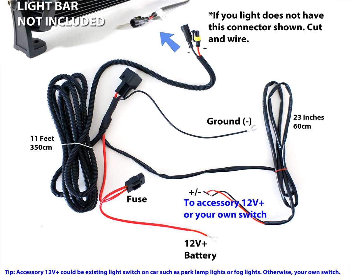
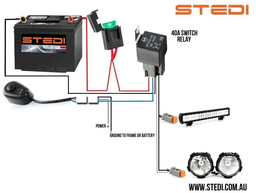
An LED light bar switch diagram also typically includes wiring connections. These connections may vary depending on the specific LED light bar and vehicle setup. However, the basic wiring connections usually consist of a power wire that connects to the battery, a ground wire that connects to the vehicle’s chassis, and a wire that connects to the LED light bar itself. It’s important to follow the manufacturer’s instructions and diagrams to ensure proper wiring and avoid any potential electrical issues.
Led Light Bar Switch Diagram
In order to install and control an LED light bar, it is important to understand the circuit connections and switch diagram. This diagram provides a visual representation of how the switch should be connected to the LED light bar and the power source. By following the diagram, you can ensure that the light bar is properly powered and controlled.
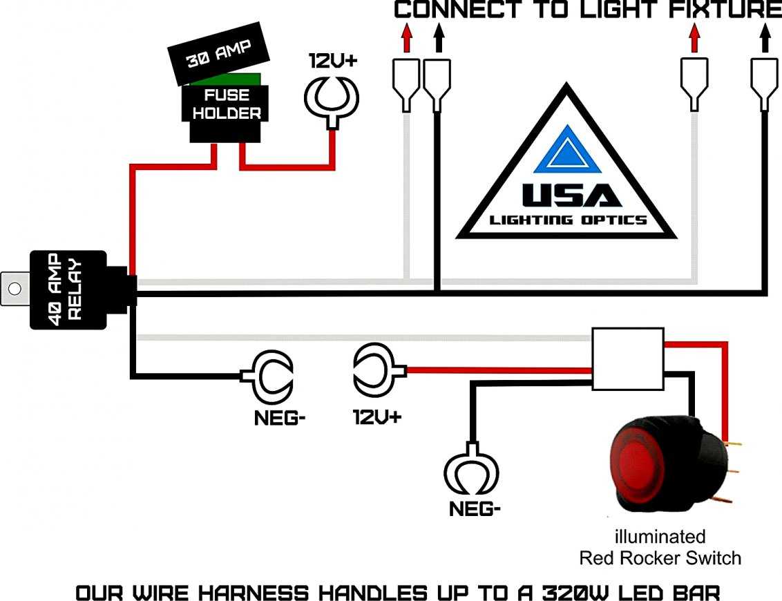
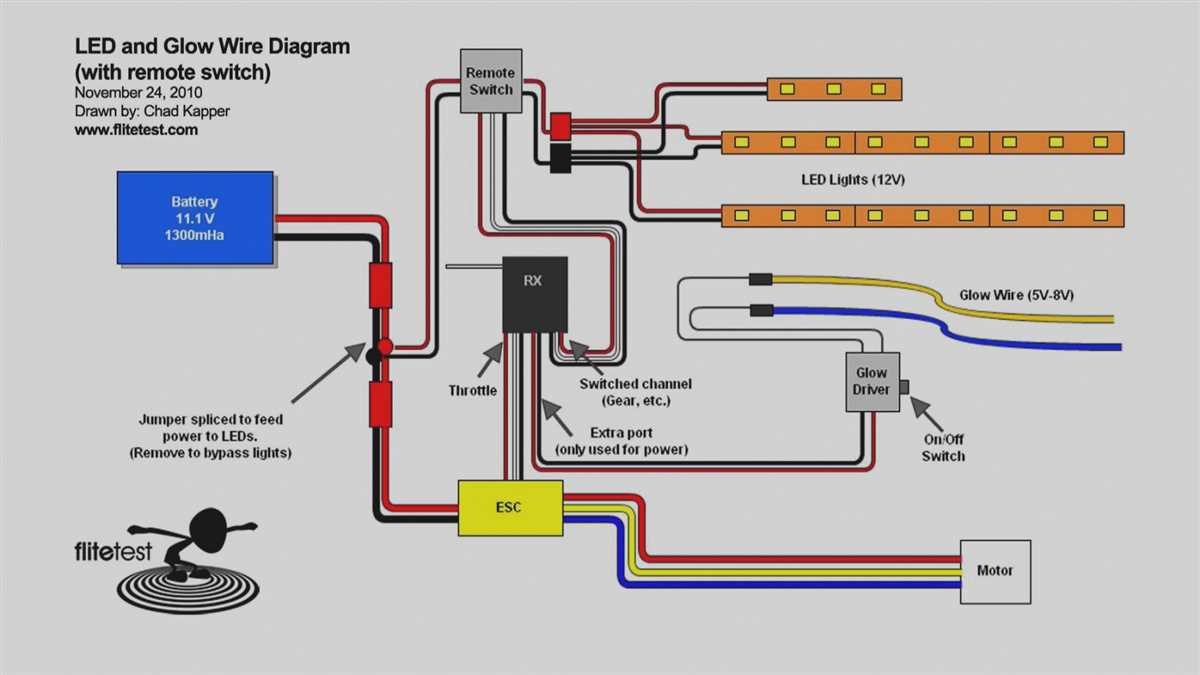
The switch diagram typically consists of several components, including the power source, switch, fuse, relay, and the LED light bar itself. These components are connected using wires and connectors, which are represented by lines in the diagram. The diagram also includes labels and symbols to indicate the type and purpose of each component.
Power Source: The power source is usually a battery or a vehicle’s electrical system. It provides the electrical energy needed to power the LED light bar. In the diagram, the power source is represented by a labeled symbol.
Switch: The switch controls the on/off function of the LED light bar. It is connected to the power source and the light bar using wires. The switch can be a simple on/off switch or a more complex multi-position switch, depending on the desired functionality.
Fuse: The fuse is a safety device that protects the circuit from excessive current. It is typically installed between the power source and the switch. If the current exceeds a certain limit, the fuse will blow, interrupting the circuit and preventing damage to the LED light bar.
Relay: The relay is an electromechanical device that acts as a switch controlled by an electrical signal. It allows a low-power signal from the switch to control the high-power circuit of the LED light bar. The relay is typically connected between the switch and the light bar.
LED Light Bar: The LED light bar is the main component of the circuit. It consists of a series of LED lights mounted on a bar or panel. The light bar is connected to the switch and the power source, and it is controlled by the switch’s on/off function.
In summary, the LED light bar switch diagram is a visual representation of how the switch, power source, fuse, relay, and LED light bar are connected in a circuit. By following the diagram and properly connecting the components, you can install and control an LED light bar with ease.
What is a LED Light Bar Switch Diagram?
A LED light bar switch diagram is a visual representation of the wiring and connections required to install and operate a LED light bar with a switch. LED light bars are popular accessories for off-road vehicles, boats, and other applications where extra lighting is needed. They provide powerful and energy-efficient illumination, making them ideal for enhancing visibility in low-light conditions.
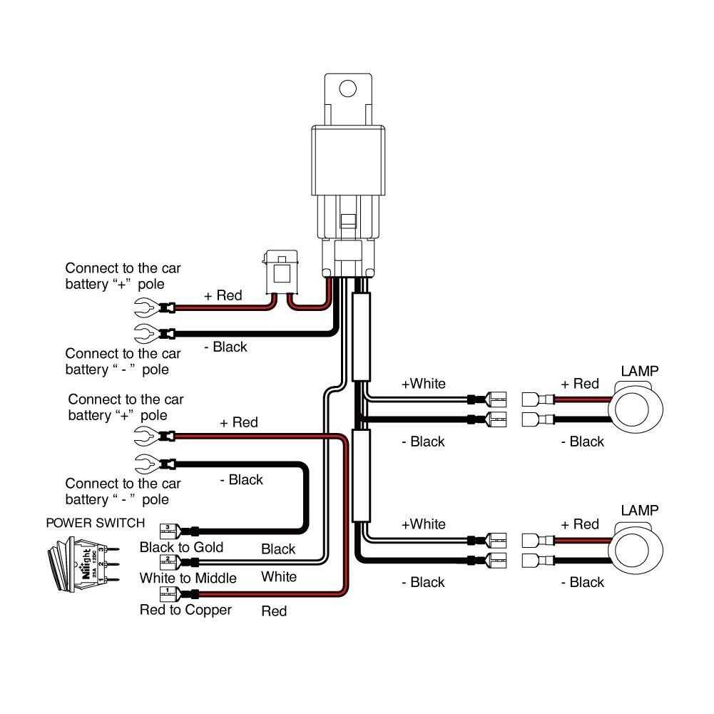
The LED light bar switch diagram shows the different components involved in the installation, including the light bar itself, the switch, and the power source. It illustrates how each component is connected and how the electrical current flows through the circuit. This diagram is essential for understanding the wiring process and ensuring proper installation and operation of the LED light bar.
The LED light bar switch diagram typically includes labels or symbols for each component, such as the light bar, switch, fuse, relay, and the connections between them. It also indicates the necessary wire sizes and colors for each connection, helping the installer to choose the correct wires and ensure a secure and reliable connection.
In addition to the basic wiring, the diagram may also include other features, such as an optional wiring harness or an inline fuse for added protection. These additional components can make the installation process easier and safer.
Overall, a LED light bar switch diagram is a valuable tool for anyone looking to install a LED light bar with a switch. It provides a clear and concise visual representation of the wiring and connections, ensuring a successful installation and proper functioning of the LED light bar.
Components of a LED Light Bar Switch Diagram
A LED light bar switch diagram typically consists of several components that are essential for the proper functioning of the switch. These components work together to control the on and off functionality of the LED light bar.
1. Switch: The switch is the primary component of the diagram and is responsible for controlling the flow of electricity to the LED light bar. It is typically a mechanical device that can be toggled between an “on” and “off” position.
2. Power source: The power source provides the electrical energy needed to operate the LED light bar. It can be a battery, a generator, or any other power supply capable of delivering the required voltage and current.
3. Wiring: The wiring connects the switch to the power source and the LED light bar. It ensures that the electrical current flows in the desired path and reaches the intended components.
4. Fuse: A fuse is often included in the switch diagram to protect the circuit from excessive current. It acts as a safety device that will interrupt the flow of electricity if a short circuit or overload occurs.
5. LED light bar: The LED light bar is the device that emits light and provides illumination. It is connected to the switch diagram and is powered on or off based on the position of the switch.
6. Indicator light: Some switch diagrams may include an indicator light that illuminates when the LED light bar is turned on. This can be useful for visual indication and to verify the status of the light bar.
Overall, a LED light bar switch diagram incorporates these components to provide a clear and organized representation of the electrical connections and functionality of the switch. It ensures that the LED light bar can be easily controlled and operated with the flick of a switch.
How to Read a Led Light Bar Switch Diagram
When it comes to installing or troubleshooting a LED light bar switch, it is important to understand how to read the switch diagram. The diagram provides a visual representation of the switch and its connections, allowing you to identify the various components and their functions.
Firstly, you might notice that the switch diagram is typically divided into two main sections: the switch itself and the connections. The switch section will show different symbols that represent the different modes or functions of the switch. These symbols can vary depending on the specific switch model, but common ones include on/off, dimming, strobe, and pattern selection.
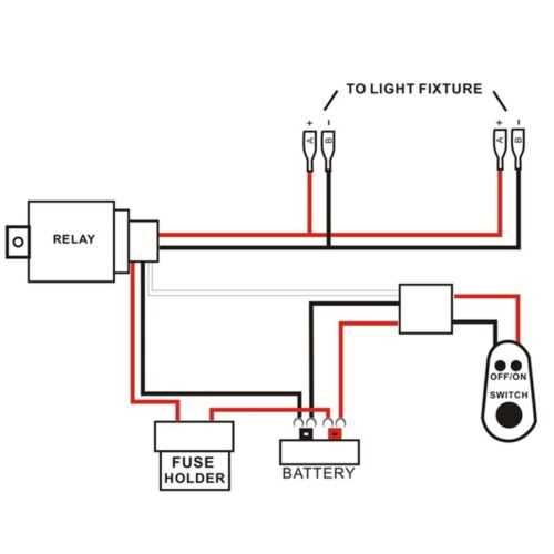
The connections section of the diagram illustrates how the switch is wired to the LED light bar and other devices. Typically, it will include labels or symbols for power sources, such as the battery, fuse, and relay. It will also show the wires connecting the switch to the LED light bar, as well as any additional components, such as a switch panel or controller.
- The power source for the switch, usually the vehicle’s battery, is indicated by a label or symbol.
- Wires connecting the switch to the LED light bar will be represented by lines or arrows, indicating the direction of current flow.
- If there are multiple switches or devices connected to the switch, the diagram may include labels or symbols to indicate their respective functions or connections.
By carefully studying the switch diagram, you can determine how the switch operates and how it is connected to the LED light bar. This knowledge can be helpful for troubleshooting any issues or for properly installing the switch in your vehicle.
Common Wiring Configurations for LED Light Bar Switches
When installing an LED light bar in your vehicle, it is crucial to have a switch installed to have control over the light. The switch allows you to turn the light bar on and off as needed, providing convenience and flexibility. There are several common wiring configurations for LED light bar switches that you can consider for your installation.
1. Single Pole Single Throw (SPST) Configuration: This is the simplest wiring configuration for an LED light bar switch. It consists of a single switch that connects or disconnects the power supply to the light bar. When the switch is in the ON position, the light bar will turn on, and when it is in the OFF position, the light bar will turn off.
2. Single Pole Double Throw (SPDT) Configuration: This wiring configuration adds an extra position to the switch, allowing for more versatility. In addition to the ON and OFF positions, the SPDT switch also has a third position, usually labeled as “AUTO” or “AUTO/OFF.” In the AUTO position, the light bar is connected to a power source that automatically turns on when the vehicle’s ignition is on. In the OFF position, the light bar is completely disconnected from power.
3. Multi-Pole Multi-Throw (MPMT) Configuration: This is a more advanced wiring configuration that allows for even greater control over the light bar. It consists of multiple switches and positions, giving you the ability to control different functions of the light bar independently. For example, you can have separate switches for turning the light bar on and off, adjusting its brightness, or changing its color.
When choosing a wiring configuration for your LED light bar switch, consider your specific needs and preferences. The SPST configuration is usually sufficient for basic on/off control, while the SPDT and MPMT configurations offer more versatility and customization options. Make sure to follow the manufacturer’s instructions and consult a professional if you are unsure about the wiring process.
Troubleshooting LED Light Bar Switch Diagrams
LED light bar switch diagrams are essential for properly installing and operating LED light bars in various applications. However, like any electrical component, issues may arise, requiring troubleshooting to identify and fix the problem. Here are a few common troubleshooting steps to consider when dealing with LED light bar switch diagrams.
1. Check the Power Supply
The first step in troubleshooting LED light bar switch diagrams is to check the power supply. Ensure that the power source is providing the correct voltage and amperage necessary for the LED light bar to function properly. Use a multimeter to measure the voltage and amperage at the power source and verify that it matches the requirements specified in the switch diagram.
2. Inspect Wiring Connections
Next, inspect the wiring connections in the LED light bar switch diagram. Check for loose or damaged wires, and ensure that all connections are securely attached. A loose or faulty connection can cause the LED light bar to malfunction or not turn on at all. Additionally, make sure that the wiring is properly insulated and protected from moisture or other potential hazards.
3. Verify Switch Functionality
If the power supply and wiring connections appear to be in good condition, the next step is to verify the functionality of the switch itself. Check if the switch is properly connected and functioning as intended. Use a multimeter to test for continuity between the switch terminals and ensure that it is properly toggling the power supply on and off.
4. Check LED Light Bar Compatibility
In some cases, LED light bars and switch diagrams may not be compatible due to differences in voltage or wiring configurations. Double-check the specifications of both the LED light bar and switch diagram to ensure they are compatible with each other. If there is a mismatch, consider replacing either the LED light bar or the switch to ensure proper functionality.
5. Seek Professional Assistance
If the troubleshooting steps mentioned above do not resolve the issue with the LED light bar switch diagram, it may be necessary to seek professional assistance. An electrician or automotive technician experienced in working with LED light bars can provide expert diagnostics and repair services to get the LED light bar functioning correctly.
By following these troubleshooting steps, you can identify and resolve potential issues with LED light bar switch diagrams, ensuring proper functionality and optimal performance in your lighting setup.
Tips for Installing a Led Light Bar Switch Diagram
Installing a led light bar switch diagram can greatly enhance the functionality and convenience of your LED light bar. Here are some tips to help you with the installation process:
- Plan the installation: Before you start installing the switch diagram, it is important to plan out the installation process. Determine the best location for mounting the switch and ensure that you have all the necessary tools and materials.
- Read the instructions: It is crucial to read and understand the instructions provided with the switch diagram. This will ensure that you install it correctly and avoid any potential issues.
- Check compatibility: Make sure that the switch diagram is compatible with your LED light bar and other components. This will help avoid any compatibility issues and ensure proper functionality.
- Secure wiring connections: Properly secure all wiring connections to ensure a reliable and safe installation. Use appropriate connectors, soldering, or crimping techniques to make secure connections.
- Test the switch: After installation, test the switch to ensure it is working correctly. Check that the LED light bar turns on and off as expected and that the switch functions properly.
- Maintain proper wiring: It is important to properly route and protect the wiring during the installation. Use wire looms, zip ties, or other methods to organize and protect the wiring from damage.
- Follow regulations and guidelines: Ensure that you follow all local regulations and guidelines for the installation of the LED light bar switch diagram. This may include proper placement, wiring, and safety requirements.
By following these tips, you can ensure a smooth and successful installation of your led light bar switch diagram. Enjoy the enhanced functionality and convenience that it brings to your LED light bar setup!
Q&A:
What is a LED light bar?
A LED light bar is a long, narrow strip of LED lights that is commonly used in off-road vehicles, trucks, and other vehicles as an auxiliary lighting source. It provides bright and powerful lighting for improved visibility and safety.
Why would I want to install a LED light bar?
Installing a LED light bar can provide you with additional lighting for improved visibility, especially during night drives or off-road adventures. It can enhance your safety and the appearance of your vehicle. The LED lights are also energy-efficient and long-lasting, making them a popular choice for automotive lighting.
What is a LED light bar switch diagram?
A LED light bar switch diagram is a visual representation or diagram that shows the wiring connections and setup of the switch used to control the LED light bar. It helps in understanding the correct installation process and ensures that the switch is connected properly for smooth operation of the light bar.
Can I install a LED light bar switch diagram myself?
Yes, it is possible to install a LED light bar switch diagram yourself if you have some knowledge and experience with automotive electrical systems. However, if you are not confident in your skills, it is recommended to seek professional help to ensure a safe and proper installation.
What is a LED light bar switch diagram?
A LED light bar switch diagram is a graphical representation that illustrates the wiring and connections needed to install a LED light bar switch in a vehicle.