and understands the Safety Instructions contained in this manual. .
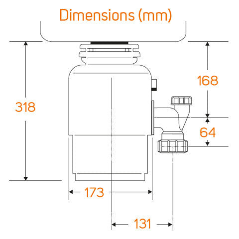
The InSinkErator Foodservice food waste disposer is. UL® and CSA® Start/stop switch (Control Center). • Sink or ..
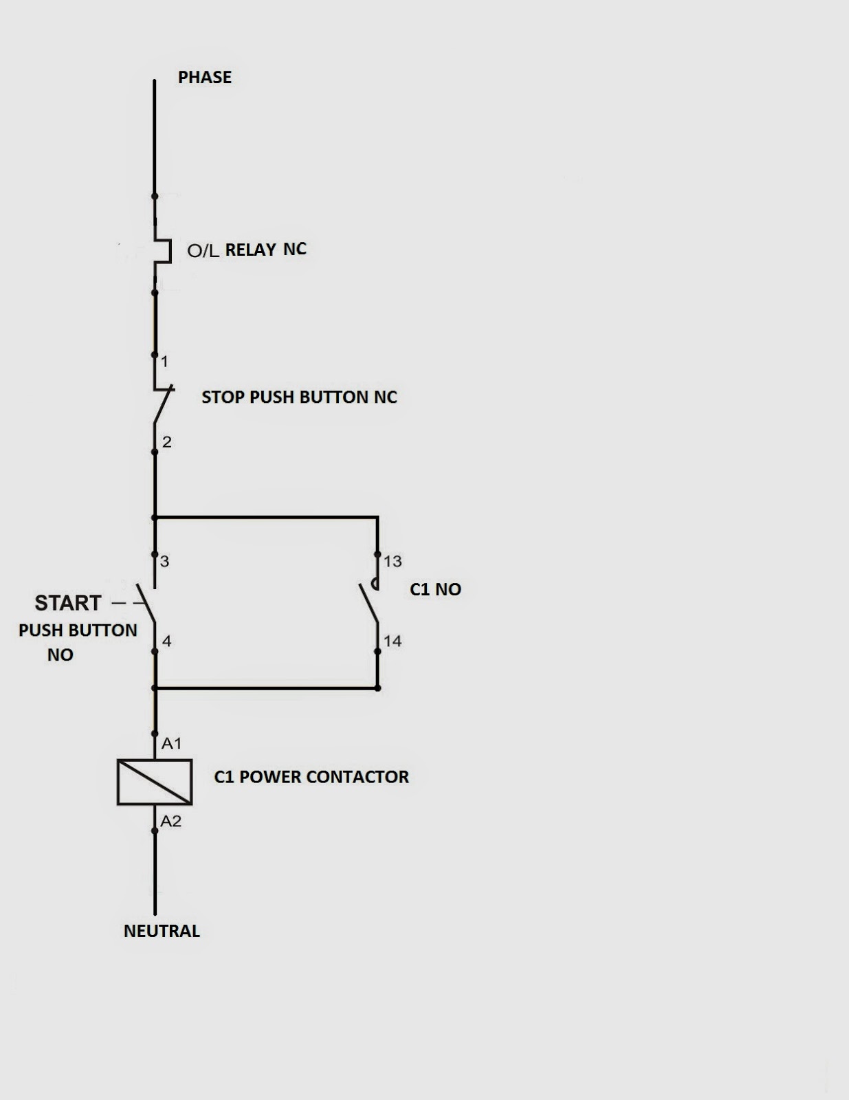
NOTE: The Manual Reversing Switch uses three-. InSinkErator, Control Center, MS, manual 2 button ON OFF switch, magnetic .
Salvajor, Start Stop Push Button, manual reversing control, NEMA 4 stainless. reads and understands the Safety Instructions contained in this manual.

The Danger signal . The InSinkErator® Waste Xpress®, disposer and control centers are warranted against defects in material and To start and stop the disposer/Waste Xpress system.
. C.
Install gaskets, cap and inlet fitting on reverse side. InSinkErator–Control Center CCD-7 with Auto Reverse and Start/Stop Buttons Controller Manual Reversing Switch MRS Volt 3 Phase.
An Auto-Reverse Grind System® feature automatically reverses grind direction, ensuring grind elements wear evenly for Includes garbage disposer, flange, stopper, Quiet Collar® sink baffle, Jam-Buster™ wrench, assembly components, Quick Lock® components and user’s manual. .. Evolution Cover Control® Plus.diagrams at the back of this manual.

Wire the disposer motor for the correct voltage using the connection diagram inside the motor terminal box. Make sure the solenoid valve is the same voltage as the control panel and supply power.
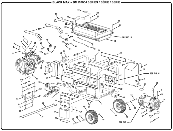
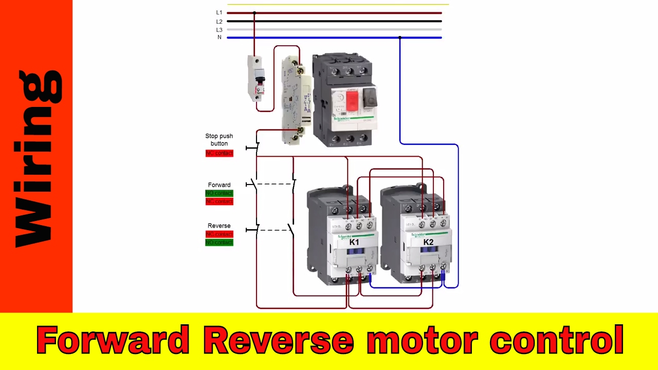
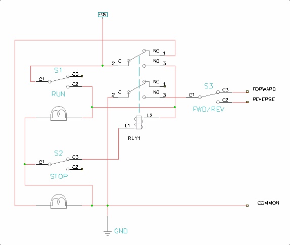
Connect water solenoid valve as shown in the wiring diagrams on pages 7, 8, 9, and Typical Wiring Diagrams For Push Button Control Stations 3 Genera/ Information @ Each circuit is illustrated with a control circuit (continued) schematic or line diagram and a control station wiring diagram. l The schematic or line diagram includes all the components .
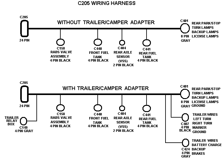
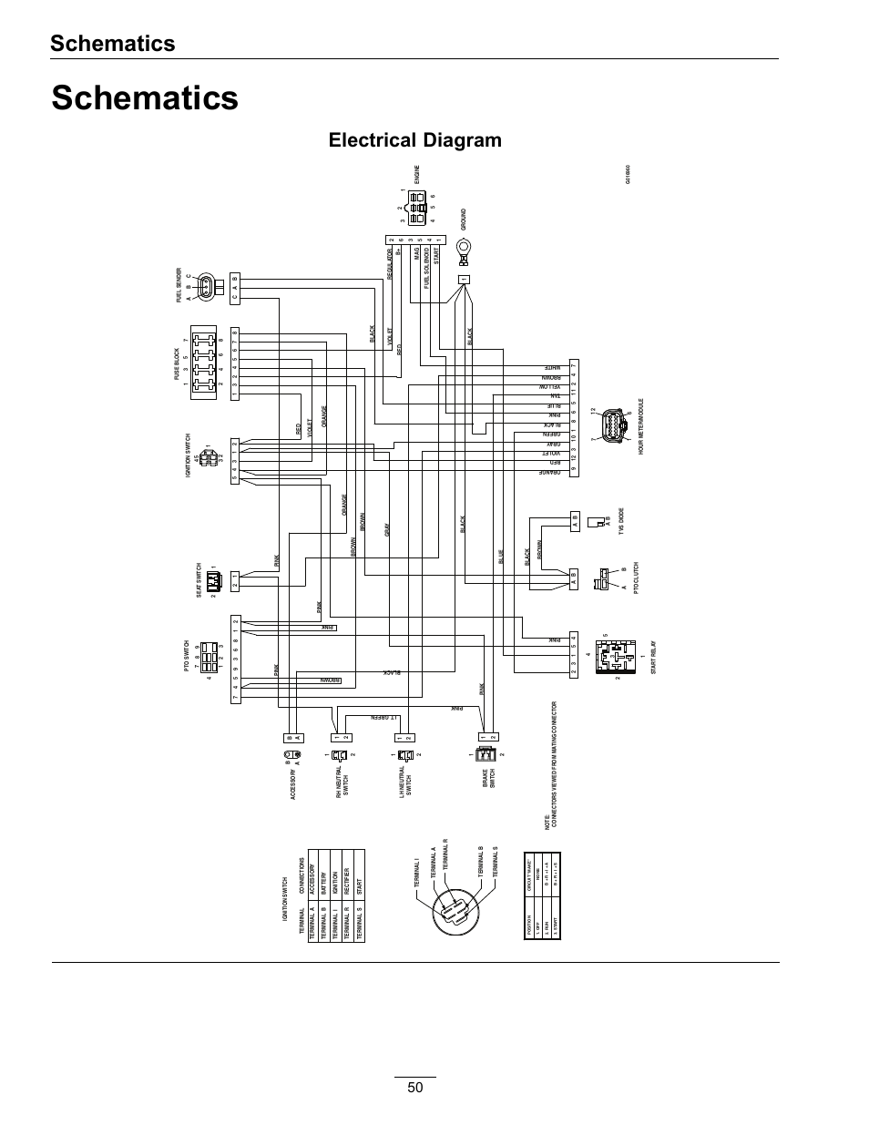
/ V 3-phase 1/2 to 10 HP Call Toll Free for the nearest InSinkErator Authorized Service Agency or to reach Technical Support. MS-6 Wiring Diagram P/N B • Ensure that the control center voltage and phase match the disposer motor and electrical supply.
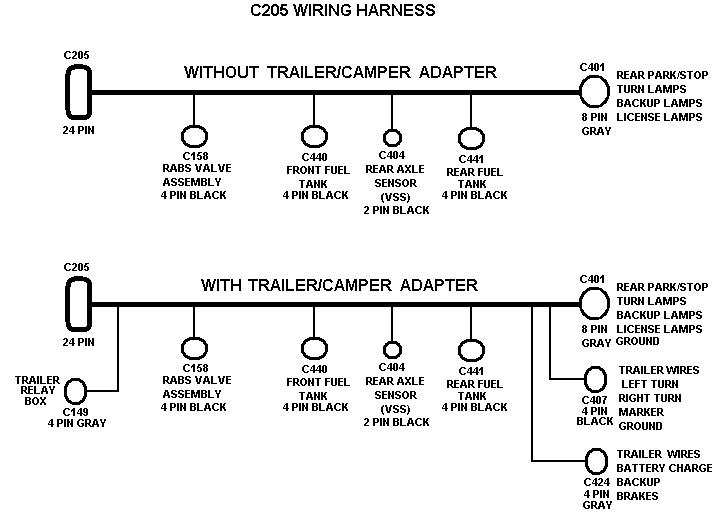
2. Install the violet wire from the Main Speed Potentiometer assembly (removed in step 1) to the center terminal of the Forward-Stop-Reverse Switch assembly.
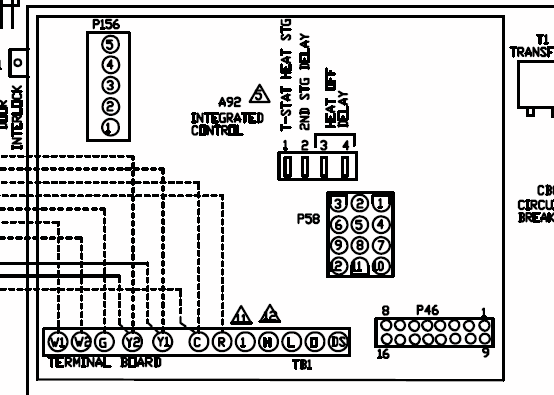
See Figure 2. 3.
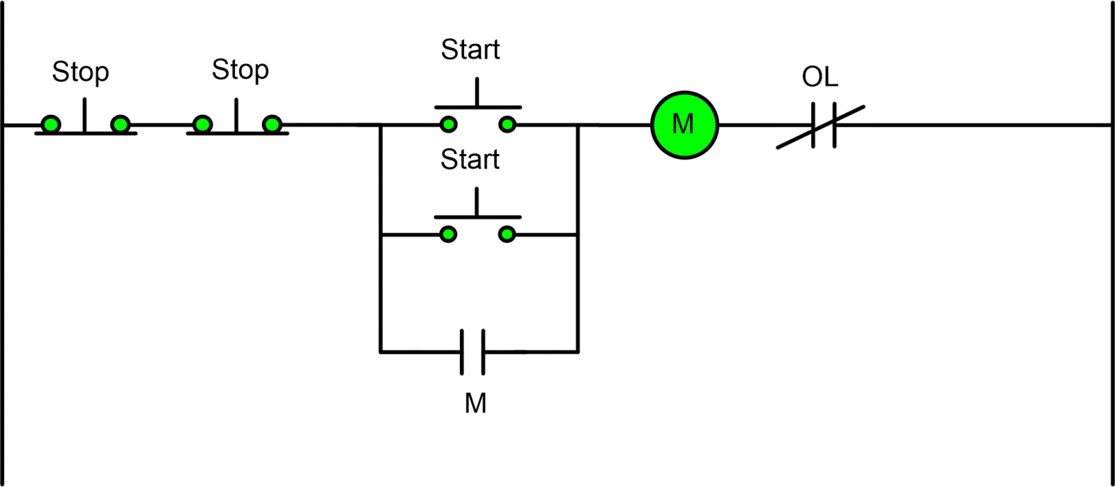
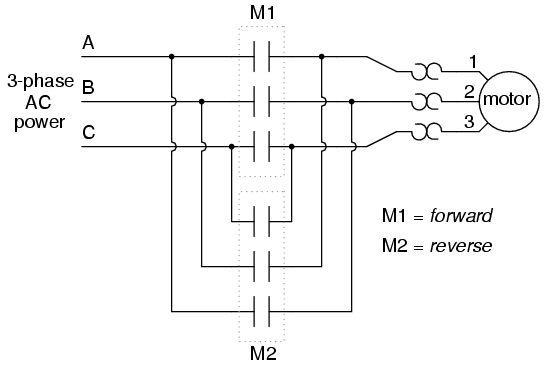
Install the white/yellow wire from the Forward-Stop-Reverse Switch assembly to the +15V terminal of . Oct 22, · Figure 5 – Forward/reverse motor wiring diagram In this wiring diagram, both the forward and reverse coils have their returns connected to L2 and not to the overload contacts. The overload contacts are connected to L1 on one side and to the PLC’s input module on the other (input ).InSinkErator MS-8 Manual Switch Single-Direction Control CenterINSINKERATOR MS MS INSTALLATION MANUAL Pdf Download.
