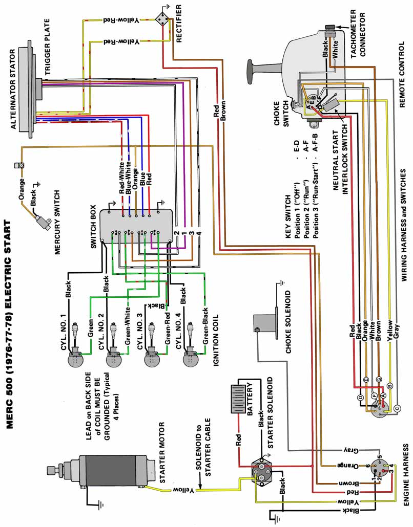
Image Of Template Mercruiser Thunderbolt Ignition Wiring Diagram.
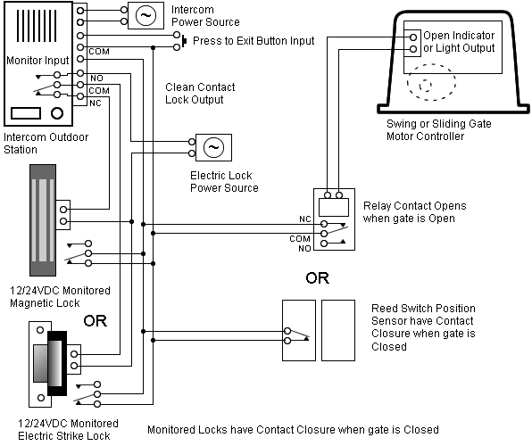
Diagram. Mercruiser Thunderbolt Ignition Wiring Diagram.
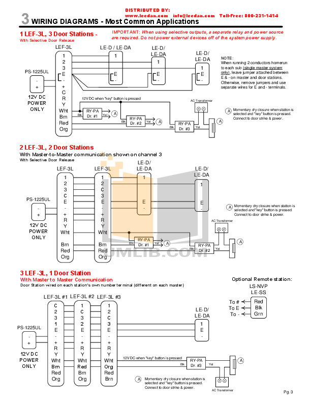
Mercruiser Thunderbolt Ignition . Mercruiser introduced the Thunderbolt IV onto their engines in , plug and the interconnect wires became part of the engine harness.
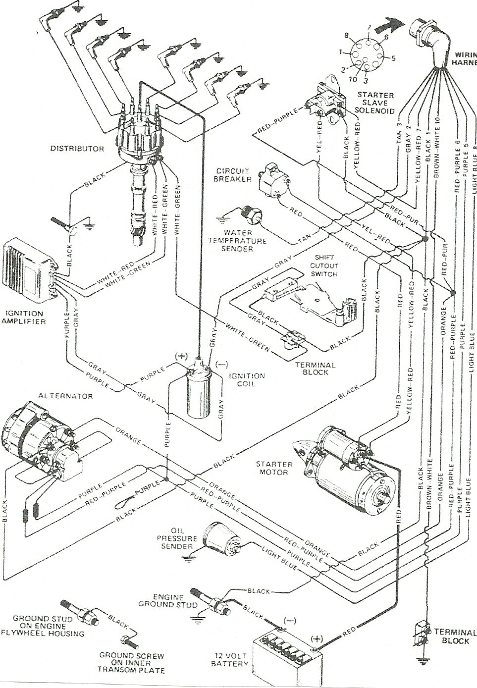
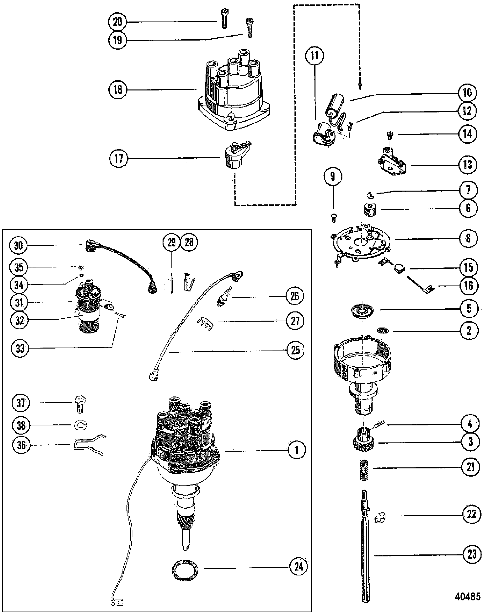
Below is a diagram showing how the various parts of the system connect together. Mercruiser thunderbolt iv amplifier mercruiser engine parts diagram mercruiser thunderbolt iv wiring diagram mercruiser thunderbolt iv. Thunderbolt IV mounted on exhaust elbow wht/red from module to dis.
Announcement
wht/grn from module to dis. gray neg on coil to tac.
and to module. purple. Wiring Colors for MerCruiser.
4D-1 4D MPI Wiring Diagram. 4D MCM V-6 Gen + Alpha Thunderbolt V Without Knock Sensor.
1. 2.
3. 1.
2. 3.
4.MerCruiser l bravo (gen. v) gm v-8 wiring harness/electrical(thunderbolt v ignition) parts. Buy a genuine Mercury Quicksilver or aftermarket part.
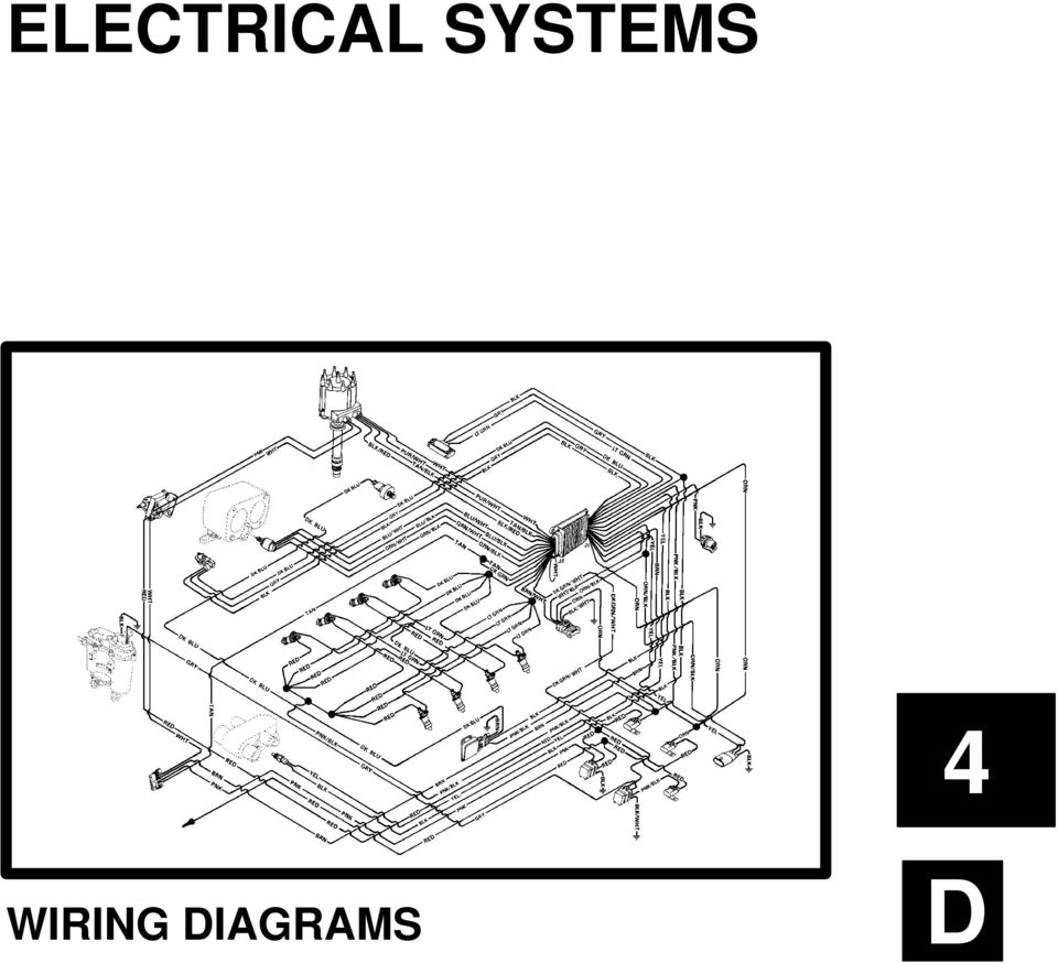
ELECTRICAL SYSTEMS IGNITION SYSTEM. 4B-0 – IGNITION SYSTEM Table of Contents Thunderbolt V Ignition System Wiring Diagram. IGNITION SYSTEM – 4B-7 Ignition Timing the DLC connector of the wiring harness.
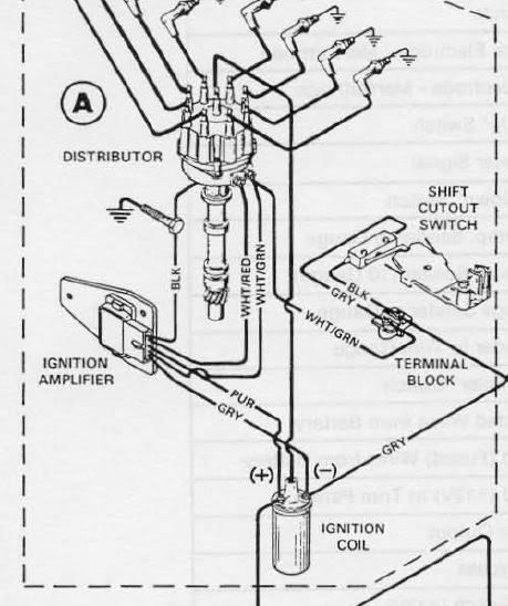
4. If Not Using MerCruiser . Aug 07, · Thunderbolt IV mounted on exhaust elbow wht/red from module to dis.
wht/grn from module to dis. gray neg on coil to tac.
414-2770 – Mercury Outboard Engine Wiring Harness – CDI Electronics
and to module. purple on pos.
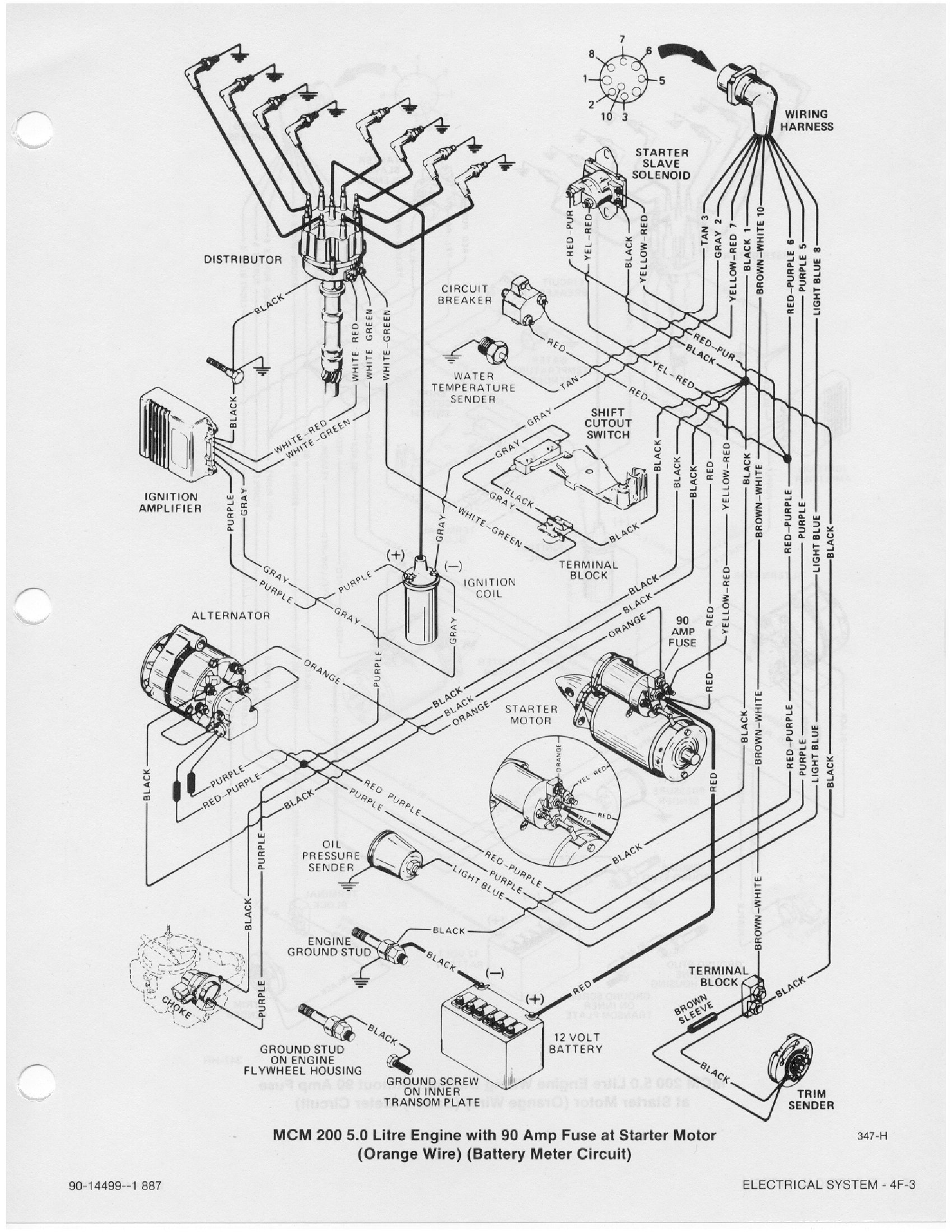
coil from module and kill switch /ignition. blk. is ground.
Find great deals on eBay for mercruiser wiring schematron.org Money When You Sell · Returns Made Easy · Fill Your Cart With Color · Top Brands. Buy Mercruiser service manuals and repair manuals by Seloc direct from schematron.orgational Shipping · Flat Rate · Fuel Systems · Safety Products.Diagram: Mercruiser Thunderbolt Ignition Wiring DiagramDiagram: Mercruiser Thunderbolt Ignition Wiring Diagram
