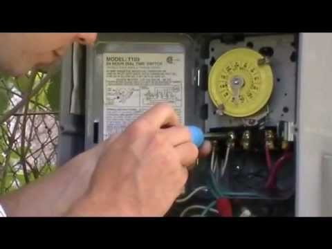
Currently, there are two white wires from A & 1 leading to the timer itself.
My question is, in which locations (1 thru 4) do I wire the black and. WIRING INSTRUCTIONS: To wire switch follow diagram above. Use solid or stranded COPPER INTERMATIC INCORPORATED.
SPRING GROVE, ILLINOIS. Intermatic T timer can be wired to control Volt circuit -or- Volt circuit. The key is that the T Wiring: How to wire T and T series timers.

The T Series Mechanical Time Switch has proven it can stand the test of time. These dependable time switches can handle electrical loads up to 40 A per.
The T Series Mechanical Time Switch has proven it can stand the test of time. These dependable time switches can handle electrical loads up to 40 A per.The Intermatic 40 Amp Volt SPST Electromechanical Time Switch with Indoor Enclosure is designed for industrial, commercial and residential applications. This is an CSA certified product for safety. It is ideal for general purpose schematron.org: $ Fulfillment by Amazon (FBA) is a service we offer sellers that lets them store their products in Amazon’s fulfillment centers, and we directly pack, ship, and provide customer service for these products.
Product Description. Heavy-duty mechanical time switches control a single load From the Manufacturer.
These heavy-duty Mechanical Time Switches are designed for commercial, industrial and residential applications and have the highest motor load ratings in the industry. View and Download Intermatic T supplementary manual online.
24 HOUR DIAL TIME SWITCH. T Switch pdf manual download.T Intermatic Timer | Electrical | Handyman WIRE – Handyman USAIntermatic TR Volt DPST 24 Hour Mechanical Time Switch with Outdoor Case – – schematron.org
