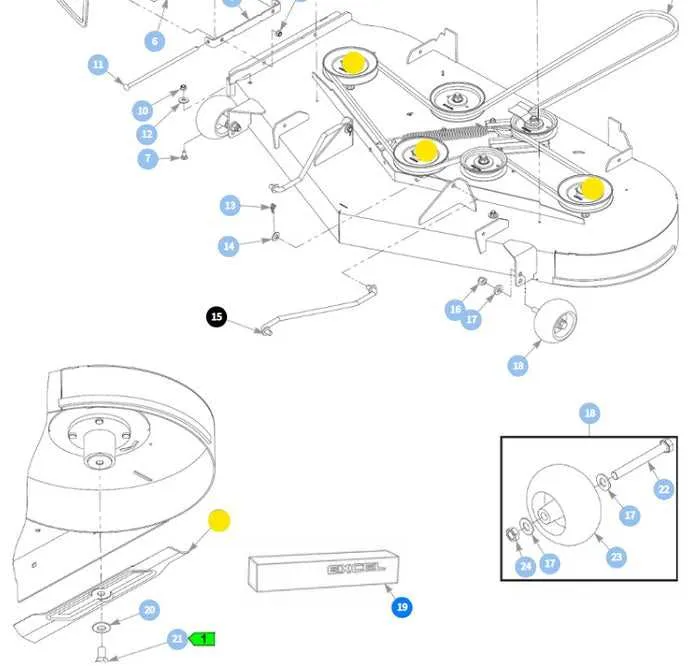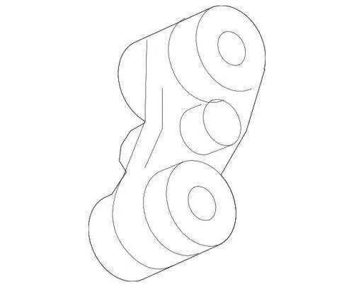
For optimal performance, always ensure the drive system is correctly assembled, especially the components responsible for transferring power from the engine to the wheels. The routing of each component must match the manufacturer’s specifications to prevent unnecessary wear and maximize efficiency. Incorrect installation can lead to premature damage or malfunction.
Start by referencing the specific schematic for your mower’s power transmission system. The main elements to pay attention to include the engine pulley, the main transmission pulleys, and the various tensioning components that control movement. Ensure that all pulleys are aligned properly and that the correct amount of slack is maintained on each segment of the powertrain.
Key tip: Double-check the spring tensioning mechanism. A too-tight or too-loose spring can cause slipping or strain on the system, both of which can decrease the tractor’s lifespan and performance. If you’re uncertain about spring strength or positioning, consider replacing it with a new one that matches the required specifications.
For a comprehensive view, review the specific blueprint for this model’s drive assembly to avoid mistakes in the reassembly process. This will provide a clear representation of where each component should sit, ensuring everything functions as intended.
Important: Always use OEM parts when replacing any components to maintain factory performance and safety standards. Keep the system clean and lubricated for long-term reliability.
Maintenance Guide for Tractor Drive System
To ensure smooth operation of the tractor’s power transmission, carefully follow the steps below for belt placement and tension adjustments.
- Locate the engine pulley and rear wheel drive components to begin the process.
- Remove any protective covers to access the drive system.
- Inspect the condition of each component, paying attention to wear on pulleys and the routing path of the power transmission loop.
- Start by positioning the loop along the path, ensuring it follows the manufacturer’s guidelines for correct placement around pulleys.
- Ensure there is no slack in the loop; the correct tension can be determined by pressing the loop with moderate force at the center of the longest run.
If you encounter difficulty during installation, check for misalignment or incorrect pulley positions, as these may cause improper loop placement.
Additional Tips
- Before reinstalling any covers, manually rotate the components to ensure smooth movement.
- If a replacement loop is needed, ensure the new one matches the required length and material specifications for optimal performance.
- Regular maintenance includes inspecting the loop every 50 hours of operation for wear and tear.
How to Read the GT235 Lawn Mower Pulley Layout

Start by locating the main components in the mower’s drive system: pulleys, tension springs, and the drive system itself. Identify the engine pulley, driven pulleys, and any idler pulleys that direct the motion of the rotating parts. Pay attention to how the lines indicating the routing path are laid out–ensure the path is continuous, with no sharp angles or twists that could lead to wear or misalignment.
Next, check the direction of rotation for each pulley. Typically, this can be found next to the pulleys themselves or inferred from the arrows on the routing schematic. Understanding the flow of motion is crucial for troubleshooting any issues such as a slipping or binding system.
Also, note any special instructions related to the tensioning mechanism. For example, certain layouts may feature spring-loaded tensioners that automatically adjust the tightness of the drive system. Be sure to understand how these components interact with the rest of the parts to ensure smooth operation.
If the mower has a multi-speed transmission, the routing will reflect additional steps for shifting between gears. Each part needs to be securely in place, ensuring the drive components operate efficiently without unnecessary friction.
Steps for Replacing the Drive Loop on the 18-HP Lawn Tractor
Disconnect the ignition lead and engage the parking brake immediately to eliminate accidental starts.
1. Lower the mowing deck fully; measure and note the current pulley layout with a photo for reference.
2. Remove the deck by releasing both rear draft arms, front hanger rod, and the spring-loaded tension rod–use a 13 mm wrench and record bolt lengths: 30 mm rear, 35 mm front.
3. Mark rotational direction on each idler using chalk; incorrect orientation shortens service life by up to 25 %.
4. Slip the worn power loop off the engine sheave first, then snake it around the center spindle and idler assemblies–note the path crosses above the right idler, below the left.
5. Inspect all pulleys: rim wear greater than 1 mm or bearing play over 0.4 mm requires replacement–ignore this and tension will drift.
6. Thread the new V-rib (OEM length 1380 mm, profile 5/8 × 107 in) along the identical route; ensure the printed code faces outward to prevent twisting.
7. Re-engage the spring arm while levering the idler with a 15 mm socket; target tension is 42–46 N·m–verify with a torque wrench, not guesswork.
8. Reinstall the deck, aligning color-coded draft arm pins (yellow left, red right) to avoid uneven cut height.
9. Spin each spindle by hand; silence indicates proper seating. Any hiss signals misalignment–re-route before proceeding.
10. Reconnect the ignition lead, start the engine at idle, engage the mower drive for 30 seconds, then shut down and re-torque idler bolt to 45 N·m after cooling.
Tip: Log operating hours; replace the drive loop every 150 hours or when sidewall glazing appears, whichever comes first.
Common Drive Strap Problems on the 235-Series Garden Tractor
Replace the power loop as soon as glazing appears–typically after 75–100 operating hours–because friction loss at this stage reaches 12 %, doubling slip risk and raising sheave temperature to 110 °C.
Verify pulley alignment with a straightedge; deviation over 0.5 ° shreds the cord fabric within ten hours. Realign by loosening the crankshaft sheave bolt (70 N·m) and shimming the clutch bracket until runout is under 0.2 mm.
Measure tensioner spring force: factory spec is 65 lb at 150 mm extension. A reading below 50 lb indicates metal fatigue; install a new galvanized spring to restore strap preload and prevent chirping during PTO engagement.
Inspect idler bearings (6203-2RS) every season. Any radial play beyond 0.15 mm or audible rumble above 40 dB at 1 500 rpm signals imminent seizure; swap the bearing or the entire wheel to avoid loop derailing.
Keep debris shields intact. Test clearances by passing a 4 mm feeler gauge around the strap path–if the gauge snags, adjust the guard tabs to avoid rubbing that reduces cord life by 30 %.