Identify relationships accurately by distinguishing between associations, aggregations, and compositions. Use solid lines with appropriate arrows and diamonds to reflect dependencies and ownership.
Class representations must include clear compartments for attributes and operations. Pay attention to visibility indicators: ‘+’ for public, ‘-‘ for private, ‘#’ for protected members.
State transitions are best expressed with labeled arrows showing events triggering changes. Incorporate guard conditions and actions inside square brackets and slashes respectively to capture behavior precisely.
Sequence flows rely on numbered messages along arrows connecting objects or actors. Ensure lifelines and activation bars are drawn to depict the timing and control of processes effectively.
Use standard symbols consistently: rectangles for entities, ovals for use cases, and diamonds for decision points. Proper notation guarantees clarity and prevents misinterpretation in complex system representations.
Quick Reference for Visual Modeling

Use rectangles with compartments to represent classes: top for the name, middle for attributes, bottom for methods. Mark abstract classes with italicized names.
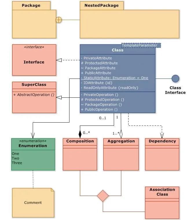
Solid lines with hollow arrows indicate inheritance relationships, pointing to the parent entity. Use dashed lines with open arrowheads for interface realizations.
Associations connect two entities with plain solid lines; label the ends with multiplicities such as 1, 0..*, or 1..*. Aggregation is shown by a hollow diamond on the container side; composition uses a filled diamond.
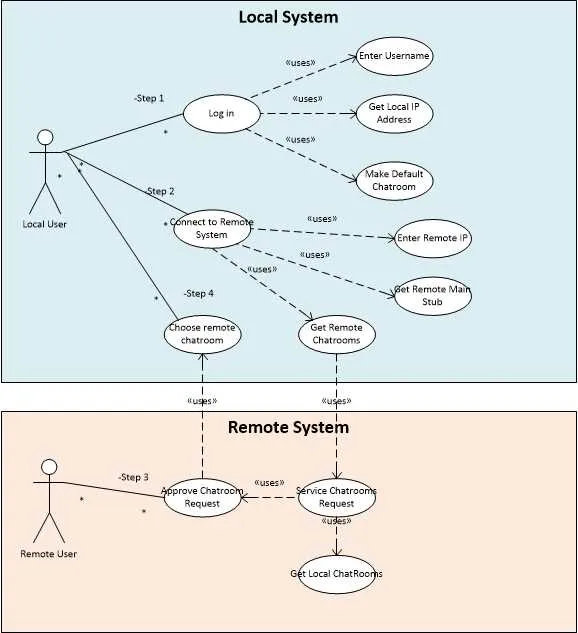
Use ovals for use cases linked by solid lines to actors represented by stick figures. Actors can be human users or external systems.
Activity flows are represented by rounded rectangles connected with arrows showing the sequence. Use diamonds to depict decision points with branching paths labeled by conditions.
State transitions should be drawn as circles connected by arrows; initial states use a filled black circle, and final states combine a circle around a black dot.
Package grouping is shown with a tabbed folder shape enclosing related components or entities, helping to organize large models.
Include notes as rectangles with a folded corner, connected by dashed lines to elements they annotate.
How to Read and Interpret Class Models

Start by identifying the main components: classes are represented as rectangles divided into three sections. The top section shows the class name, the middle lists attributes, and the bottom displays methods or operations.
Focus on the visibility symbols before attributes and methods: ‘+’ indicates public access, ‘-‘ means private, and ‘#’ marks protected elements. This helps determine which parts of the structure are accessible outside the entity.
Check the relationships connecting entities. Solid lines with hollow diamonds denote composition, implying strong ownership and lifecycle dependency. Lines with filled diamonds indicate aggregation, showing a weaker whole-part link. Arrows signify inheritance, where a subclass derives from a superclass.
Multiplicity indicators appear near the relationship ends, such as 1, 0..*, or 1..*, defining how many instances of one class relate to instances of another. This clarifies one-to-one, one-to-many, or many-to-many connections.
Look for notes or constraints attached with dashed lines; these provide additional rules or conditions that impact how entities interact or behave.
Analyze method parameters and return types listed in parentheses after method names, e.g., getName(): String, to understand functionality and expected outputs.
When you spot abstract classes, their names or methods are often italicized, signaling they cannot be instantiated directly but serve as templates for other classes.
Interfaces usually appear as classes labeled accordingly or with «interface» stereotype, highlighting contracts that other classes must implement.
Key Notations for Sequence Modeling

Focus on these core symbols to accurately represent interactions over time:
- Actors and Objects: Represented by rectangles at the top; actors typically placed outside the system boundary, objects inside.
- Lifelines: Vertical dashed lines descending from actors/objects, indicating their presence throughout the interaction.
- Activation Bars: Narrow rectangles on lifelines showing when an entity is active or controlling the flow.
- Messages: Horizontal arrows between lifelines; solid arrows for synchronous calls, open arrowheads for asynchronous signals.
- Return Messages: Dashed arrows pointing back, representing responses or results.
- Combined Fragments: Frames surrounding interaction segments to model control structures like loops (
loop), alternatives (alt), options (opt), and parallel executions (par). - Gates: Small triangles on fragment edges, defining interaction entry or exit points.
- Destruction Notation: A large “X” at the end of a lifeline indicating an object’s termination.
Applying these conventions ensures clarity in depicting message sequences, control flow, and object life cycles.
Common Mistakes When Drawing Use Case Models
Define clear boundaries for your system. Avoid mixing external actors and internal components. Actors must represent roles interacting from outside, not system parts.
Do not overload with too many use cases. Focus on primary functionalities and avoid minor or implementation-level details. Excessive elements reduce clarity.
Maintain consistency in actor representation. Each actor should appear once with a meaningful name reflecting its role. Duplicate or vague labels cause confusion.
Ensure relationships are accurate. Misuse of include and extend connections leads to incorrect behavior interpretation. Use include for mandatory reuse and extend for optional or conditional behavior.
Avoid placing too many associations between actors and use cases. Limit connections to those representing actual interactions, preventing clutter and misinterpretation.
Do not confuse use cases with user stories or system requirements. Keep use cases high-level and interaction-focused, without detailed process flows or technical specifics.
Place the system boundary box appropriately. Ensure it encloses all relevant use cases and excludes actors, visually clarifying the scope of the modeled system.
Use simple and descriptive names. Each use case should have a concise title describing the goal, avoiding vague or overly technical terms.
Check for consistency between textual descriptions and visual elements. Misalignment leads to misunderstandings and errors in interpretation.