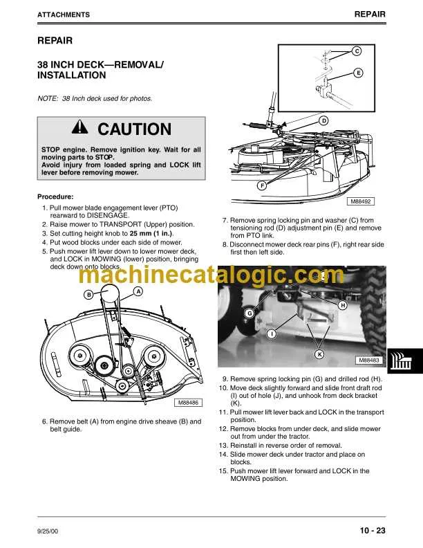
Ensure the correct positioning of the transmission and mower pulleys by following the specific layout for the primary loop system. Misalignment or incorrect threading can cause premature wear or belt slippage, impacting overall performance and safety.
Refer to the assembly schematic illustrating the tensioner, idler pulleys, and main drive path to avoid operational issues. Proper engagement with each roller and guide is critical for smooth power transfer and longevity of the mowing deck mechanism.
Maintenance and adjustment intervals should include checking this routing to prevent unexpected downtime. Utilizing the exact configuration recommended for this model avoids unnecessary strain on the engine and cutting assembly, ensuring optimal efficiency.
Drive System Routing and Tension Guide

Ensure correct routing of the primary power transmission strap by following the detailed schematic for the mower’s pulley and idler configuration. The main loop must pass precisely around the clutch pulley, engine pulley, and spindle sheaves to maintain proper engagement and avoid slippage.
Check tension adjustment points carefully: use the tensioner arm to achieve optimal tautness without over-tightening, which can lead to premature wear or damage. The tension spring location and anchor points are crucial for consistent performance.
Refer to the specific layout showing crossover points and idler wheel placement to prevent misalignment. Proper alignment reduces friction and enhances the longevity of the transmission components. Use manufacturer-recommended part numbers for replacement loops to match original specifications exactly.
Regular inspection of wear indicators on the drive strap is essential to prevent unexpected breakdowns. Replace the loop immediately if fraying, cracking, or glazing appears.
Locating and Identifying Key Drive Components on the LT155 Mower
Start by accessing the mower’s deck area to examine the primary transmission loop that connects the engine pulley to the cutting mechanism. The drive component responsible for power transfer to the blades is positioned beneath the mower deck, often partially covered by a protective shield.
Next, identify the tension pulley assembly near the engine mount, which maintains appropriate pressure on the main loop and prevents slippage during operation. This idler pulley is critical for ensuring consistent engagement and can be distinguished by its spring-loaded bracket.
Inspect the secondary power transmission line linking the engine crankshaft to the main pulley; this smaller loop controls blade engagement and should exhibit no visible cracks or fraying. Its routing follows a specific path around the engine’s spindle and idler guides.
Check the condition and alignment of the forward movement transmission loop running between the engine and the transaxle pulley. Proper tension here is essential for smooth propulsion and can be adjusted via the tensioning mechanism located near the rear of the chassis.
Finally, always confirm the orientation and correct seating of all power transfer components, as improper installation leads to rapid wear and operational failure. Refer to the machine’s service manual for exact routing to avoid incorrect placement.
Step-by-Step Guide to Replacing Drive Strap on Lawn Tractor
Begin by disconnecting the spark plug wire to ensure safety during maintenance. Remove the mower deck by loosening the mounting bolts and lowering it carefully.
Release tension on the primary pulley by sliding the idler arm away to free the old transmission loop. Note the routing path before removal to replicate installation accurately.
Take out the worn drive loop from the engine pulley, transmission pulley, and any idler wheels. Inspect all pulleys and rollers for wear or damage; replace if necessary.
Install the new strap following the original routing exactly: loop it around the engine pulley, then guide it over the idler wheels and finally onto the transmission pulley.
Apply tension by repositioning the idler arm to ensure the new loop fits snugly without excessive slack, avoiding slipping during operation.
Reattach the mower deck securely, double-checking all bolts and connections. Reconnect the spark plug wire before starting the engine to test the new drive system.
Troubleshooting Common Drive Strap Issues on the LT155 Mower
Immediately inspect the mower’s primary drive strap for cracks, fraying, or glazing, which often cause slipping or loss of power transmission. Replace any worn or damaged component to restore proper operation.
- Check tension: Ensure the drive loop maintains adequate tension. A loose loop reduces cutting efficiency and may cause overheating of pulleys.
- Inspect pulleys: Examine all guide wheels and tensioners for wear, debris, or misalignment. Damaged or seized rollers can accelerate wear on the transmission loop.
- Look for contamination: Grease, oil, or grass clippings on the strap surface lead to slipping. Clean the entire path thoroughly before reassembly.
If the propulsion mechanism hesitates or the cutting deck fails to engage, verify that the clutch and its associated connections are free of damage and securely mounted.
- Remove the deck and test the engagement mechanism manually to confirm smooth operation.
- Replace any seized or bent tension springs affecting strap alignment.
- Lubricate pivot points and moving parts to reduce friction and prolong component lifespan.
Finally, follow the maintenance intervals for replacing the transmission component to avoid unexpected breakdowns during operation. Frequent checks before mowing seasons improve reliability and cutting performance.