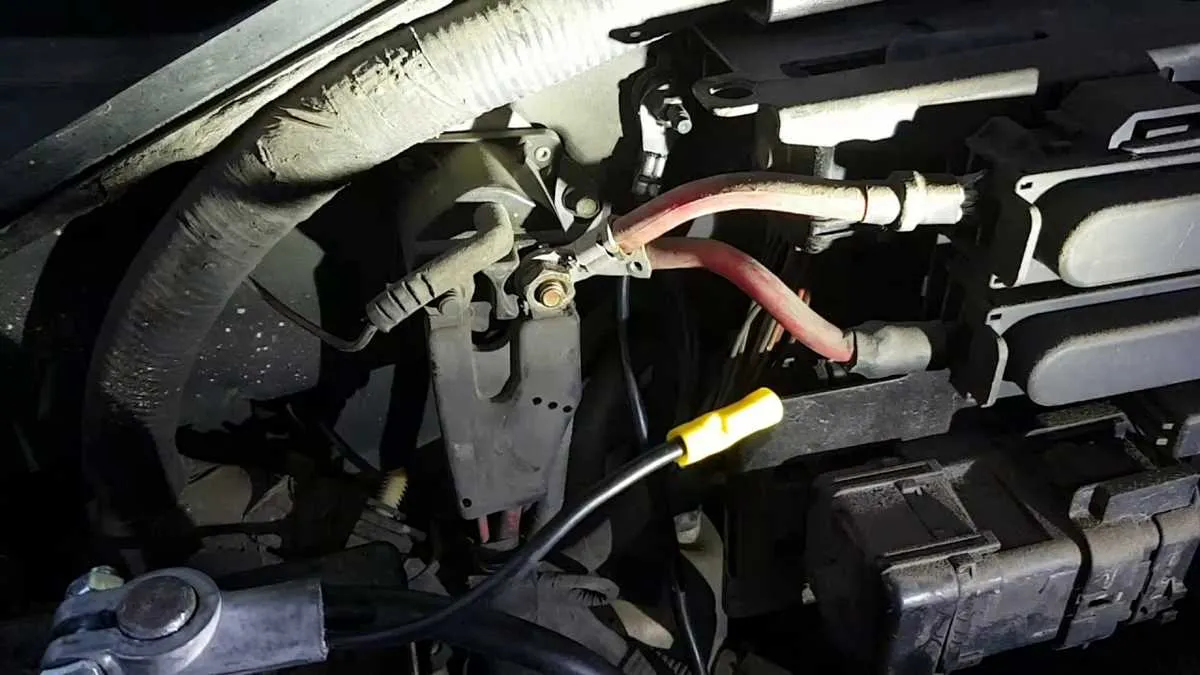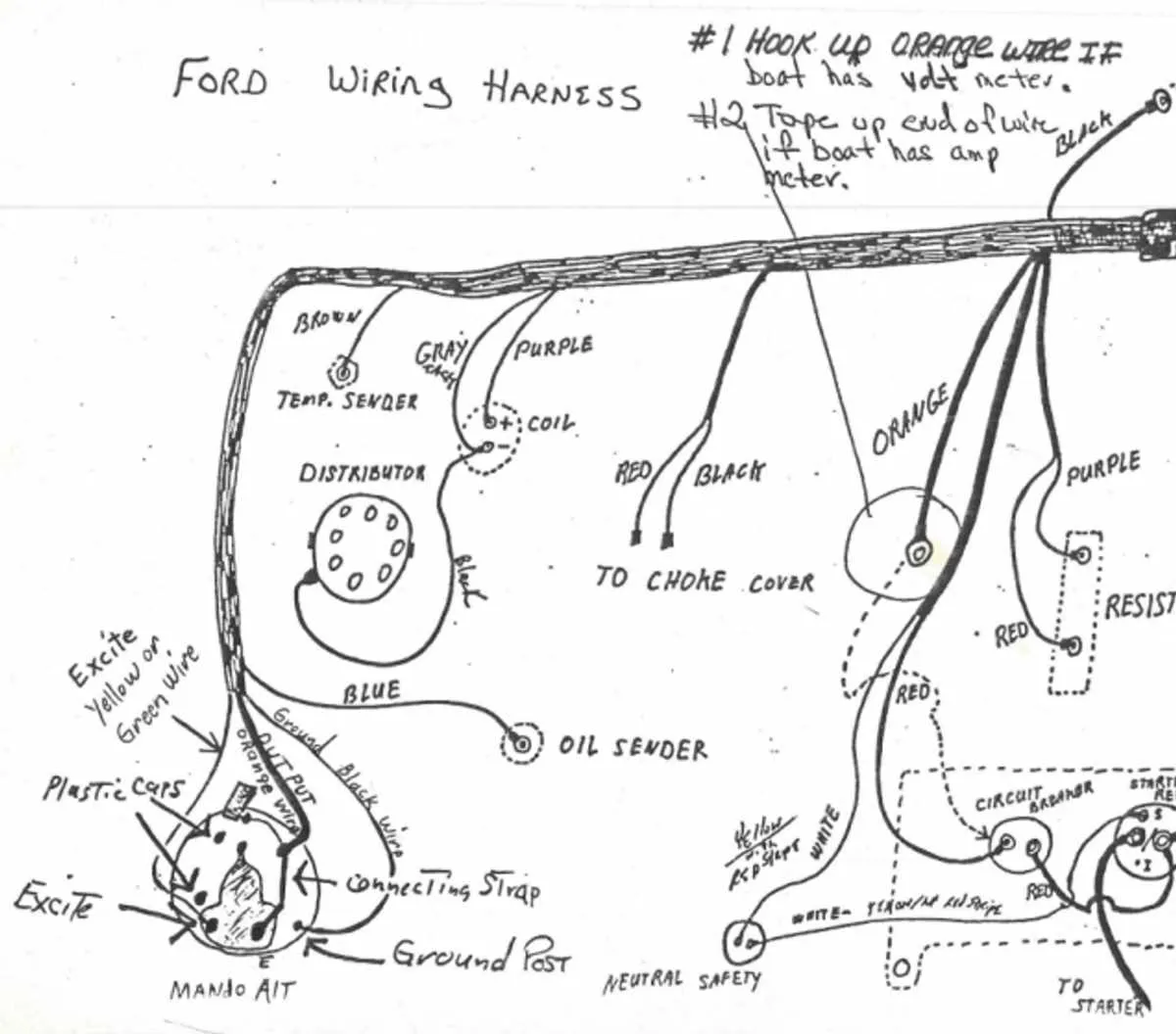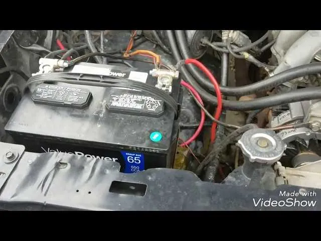
To ensure optimal electrical performance and avoid common malfunctions, the main negative cable attachment point can be found near the battery’s negative terminal, firmly secured to the vehicle’s body frame close to the engine bay. This connection point is critical for maintaining proper circuit continuity and preventing voltage drops that may affect sensitive electronic components.
Inspecting this grounding terminal reveals it is typically fastened with a bolt onto a clean, unpainted metal surface, often the inner fender or firewall area. Routine maintenance should include checking for corrosion or looseness, which can cause intermittent electrical faults or starting issues.
For advanced troubleshooting, tracing the heavy-gauge return conductor from the battery negative post will lead directly to this anchoring spot, which serves as the main earthing reference for the vehicle’s entire electrical system. Proper identification and verification of this node facilitate accurate diagnostics and safe installation of aftermarket electrical accessories.
Identifying the Main Earth Connection Points on F-Series Trucks

Start by examining the engine block area: The primary negative cable usually attaches near the front lower section of the motor assembly, often secured with a robust bolt to ensure proper conduction.
Check the chassis frame near the battery tray: A thick grounding lead connects the battery’s negative terminal to the vehicle’s main frame here, providing a critical return path for electrical circuits.
Inspect under the dashboard on the driver’s side: Multiple smaller earth straps or braided conductors are fastened to the metal framework, supporting instrument panel functions and sensor accuracy.
Also, verify the connections at the body shell close to the firewall: Several grounding terminals link electrical harnesses to the metallic structure, maintaining system stability and preventing voltage irregularities.
Regular maintenance tip: Clean and tighten all bolts securing these return pathways to avoid corrosion-induced resistance that can cause intermittent electrical faults.
Step-by-Step Guide to Tracing Earth Cable Connections in the Engine Bay

Begin by disconnecting the negative terminal from the battery to prevent electrical shorts. Locate the main chassis connection point–usually a thick black cable attached near the engine block or firewall. Follow this lead to confirm its secure attachment using a wrench to check bolt tightness and signs of corrosion.
Next, identify additional return paths linking various components such as the alternator, starter motor, and sensor grounds. Use a continuity tester or multimeter set to resistance mode, placing one probe on the engine block and the other on the cable terminals to verify a solid connection with minimal ohm reading.
Inspect junction points where multiple earth leads converge, often near the battery tray or inner fender. Clean any oxidized metal surfaces with a wire brush or sandpaper, then re-tighten fasteners to ensure optimal conductivity. Replace any damaged straps or cables showing frayed insulation or broken strands.
Confirm the integrity of harness grounds by tracing smaller return leads from sensors or control modules back to their attachment points on the frame or engine. Document each connection and test results to pinpoint any weak spots or open circuits requiring repair.
Finally, after verifying all grounding circuits, reconnect the battery terminal and perform a function test on electrical components to confirm stable voltage levels and absence of interference or noise caused by poor earth connections.
Troubleshooting Common Issues with Negative Electrical Connections and Their Impact on Vehicle Systems

Always begin by verifying the integrity of the chassis return path, as poor contact can cause voltage drops affecting multiple circuits. Use a multimeter to check continuity between the negative terminal and the vehicle frame; resistance above 0.1 ohms indicates corrosion or loose attachment points requiring cleaning or tightening.
Oxidation at fastening points often leads to intermittent faults or complete loss of signal return, resulting in malfunctioning sensors, flickering lights, or erratic gauge readings. Remove any paint or rust at connection surfaces and apply dielectric grease to prevent future degradation.
Check for broken strands or damaged insulation along the return conductor, especially near vibration-prone areas like the engine bay or suspension mounts. Replace compromised segments to restore reliable conductivity and prevent shorts.
When troubleshooting electrical anomalies such as starting difficulties or charging system errors, inspect the negative link first. A compromised path may cause charging voltage to fluctuate, triggering warning indicators or battery drain.
Use a clamp-on ammeter around the return conductor to detect abnormal current flow that might signal unintended grounds or circuit shorts. Address these issues promptly to avoid wiring harness damage or component failure.
Confirm tight mechanical connections at all bolt points, ensuring they meet torque specifications to maintain stable electrical contact under engine vibration and temperature changes.
Routine maintenance of return connections extends system longevity and stabilizes overall vehicle electrical performance, reducing unexpected faults and diagnostic time.