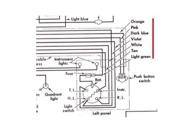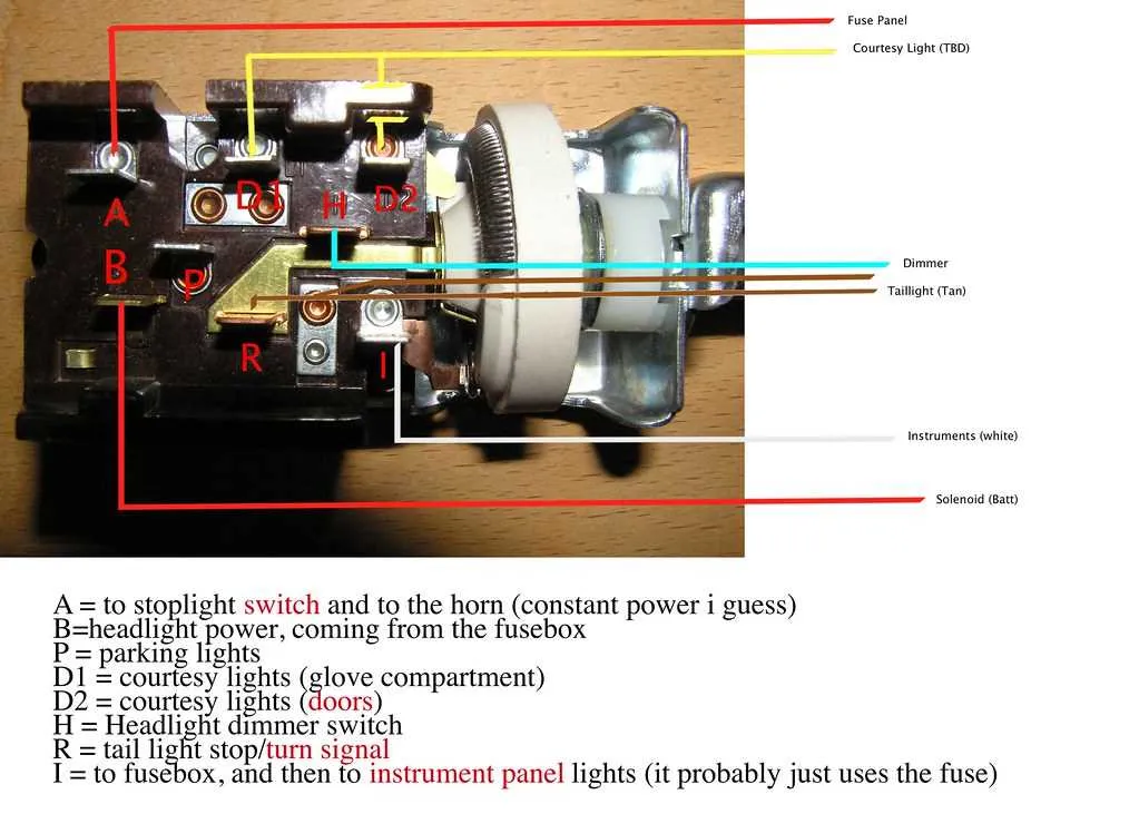
To ensure reliable operation of the front lighting controller, follow the recommended electrical schematic that clearly identifies power sources, ground points, and control terminals. Prioritize connections that maintain consistent voltage without interference, and verify that all contacts correspond to their designated pins on the actuator.
Precise identification of input and output lines is critical–use color-coded cables and labeled connectors to minimize errors during assembly or troubleshooting. Incorporate a fuse rated between 10A and 15A inline with the power feed to protect the circuit from overcurrent conditions.
Optimizing the signal path includes confirming that the illumination relay coil receives adequate current to engage promptly, preventing delay or flickering. Use a multimeter to verify continuity before finalizing any connections, ensuring that each terminal matches the factory specifications or aftermarket guidelines.
Connection Scheme of the Front Light Controller

Start by connecting the power source to the input terminal labeled “12V IN” to ensure stable voltage supply. Attach the ground wire firmly to the chassis to prevent electrical noise. The output leads marked “LOW BEAM” and “HIGH BEAM” should be linked directly to their corresponding lamp inputs using appropriate gauge wire (typically 16-18 AWG) to handle current load safely.
Incorporate a fuse rated at 15 amps inline with the power feed to protect the circuit against overloads. Use a relay if the control unit cannot handle high current, wiring the relay coil to the control terminals and the switched output to the lighting elements. Verify that the connector pins correspond precisely to the control signals indicated by the manufacturer’s pinout.
Ensure that the dimmer function is wired through the designated terminal to enable smooth beam transitions. Secure all connections with solder or crimp connectors to prevent loosening from vibration. Test continuity before final assembly to avoid shorts or open circuits that could impair illumination performance.
Identifying and Understanding Headlamp Control Terminals
Always start by locating the terminal labels on the connector block. Common markings include BAT or B+ for constant power input, IGN or IGNITION for switched power from the ignition circuit, DIM for dimmer relay feed, and GROUND or E for chassis connection.
Each pin serves a distinct function: the power feed terminal supplies voltage, the output terminals deliver current to low or high beam circuits, while the ground ensures proper circuit completion. Verify the terminal assignment using a multimeter before connecting to avoid miswiring.
Use the manufacturer’s part number or service manual to cross-reference terminal functions. Some models include additional pins for parking lamps, dashboard illumination, or fog lamp activation. Confirm which terminals correspond to these auxiliary functions.
Note that terminals designed for high current loads often have thicker connectors or heavy-gauge wires. Smaller terminals usually handle control signals. Recognizing this helps prevent overload and damage.
When replacing the unit, transfer the wiring harness carefully, matching terminal positions to maintain circuit integrity. If terminals are unlabeled, test continuity and voltage under operating conditions to map each connection accurately.
Step-by-Step Guide to Connecting the Headlight Switch Wires
Ensure the vehicle is turned off and the battery is disconnected before starting any installation or maintenance work.
- Identify the main control unit terminal and locate the wire leading to the lighting system. This wire is typically thicker and may be color-coded.
- Connect the primary wire to the terminal on the control device. Secure it tightly to prevent any loose connections.
- Find the wire responsible for the low-beam setting. This is often a separate lead, usually thinner than the main wire. Attach it to the corresponding terminal on the control unit.
- For the high-beam setting, identify the wire marked for this purpose. Connect it to the appropriate terminal, ensuring the connection is firm and insulated.
- If there’s an additional ground wire, make sure it is connected to a clean, unpainted metal surface of the vehicle chassis to ensure proper grounding.
- Double-check all connections before reattaching the battery and testing the control unit. Switch on the vehicle and test each lighting mode to confirm proper functionality.
Take care to ensure each wire is correctly attached to the right terminal. Incorrect connections may cause malfunction or damage to the system.
Troubleshooting Common Issues with Light Control Circuits
If the lighting system fails to respond correctly, start by checking the connections at the control lever. Ensure all connectors are securely plugged in without corrosion or dirt buildup. A loose or dirty terminal may cause intermittent functionality.
Next, examine the ground connections. A poor ground can lead to malfunction, preventing the lights from turning on or off properly. Clean any rust or debris around the grounding points, and ensure the metal contact is solid.
Check the integrity of the fuse linked to the system. A blown fuse is a common cause for total failure. Replace it with one of the correct amperage to avoid further damage to the circuit.
If the lights stay on when they should be off, inspect the relay involved in the circuit. A sticking or faulty relay may cause the system to remain activated even after the control lever is disengaged.
Pay attention to the control mechanism itself. Over time, wear and tear can lead to internal damage within the mechanism, causing it to fail in delivering proper signals to the rest of the circuit. In such cases, replacing the mechanism may be necessary.
For systems with multiple light settings, verify the resistance value of the associated variable resistor. If it becomes faulty, the system may fail to adjust brightness levels or could cause erratic behavior in light functions.
Finally, inspect the wiring leading to the lights for any signs of wear, cuts, or frays. Exposed wiring can cause short circuits or fail to transmit current properly, leading to partial or full system failure.