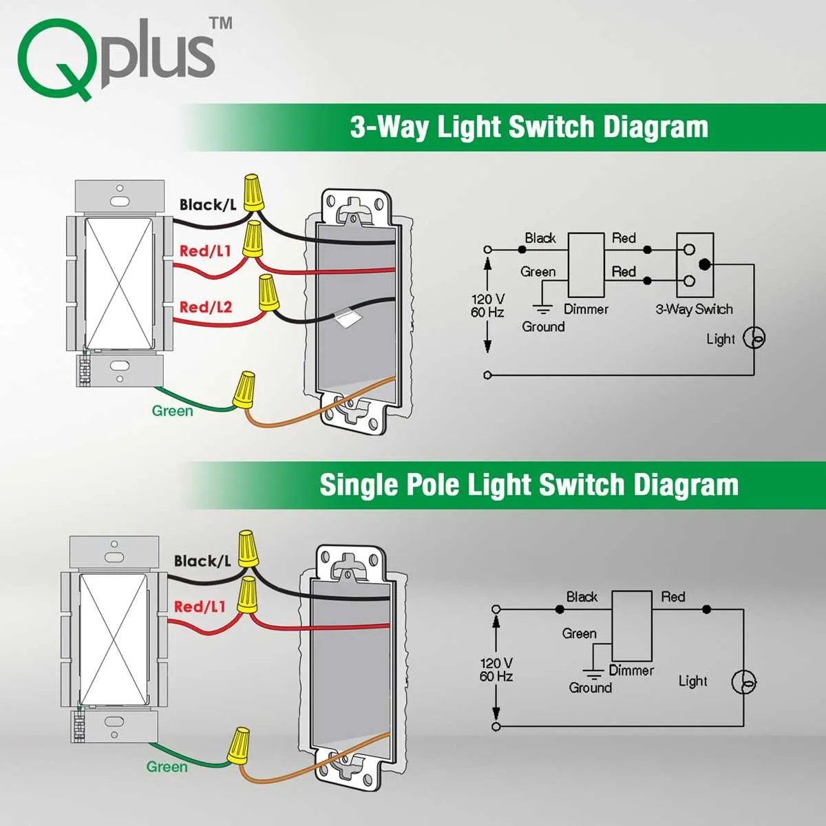
When installing a fixture with dual controls, it’s crucial to ensure proper connection of the electrical components for safe and effective operation. Always start by identifying the live wire and ensuring it is properly connected to the correct terminal of the device. This will prevent potential circuit failures and electrical hazards.
Next, verify that the traveler wires are connected accurately between the two control points. These wires enable the alternate control from either location, so ensuring they are securely attached is key to achieving seamless operation.
Also, make sure the ground wire is properly connected to the grounding screw of the unit. This will help prevent any risk of electric shock or short circuit. The importance of a secure ground connection cannot be overstated.
Final check: Once all connections are complete, carefully test the functionality of the setup. Verify the expected performance of the fixture from both control points, ensuring there is no flickering or malfunction. This last step will confirm the integrity of the installation.
Proper installation ensures not only safety but also long-term reliability of your dual-control system. Following these precise steps will result in a well-functioning, efficient electrical setup.
Wiring a Multi-Position Illuminated Circuit Control

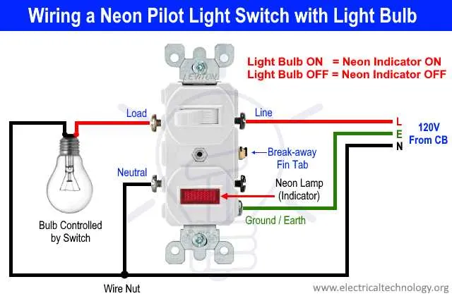
To properly install a multi-position illuminated circuit control, ensure all components are compatible with the specific electrical load and voltage requirements of your system. Start by connecting the live (hot) wire to the terminal marked for power input, typically located on the side of the unit with the most terminals. Next, connect the return wire to the appropriate terminal for the circuit you are controlling.
Ensure that the grounding wire is securely attached to the grounding terminal, which is often located separately from the other terminals. This step is critical for safety and ensuring proper function. If your model includes an illumination feature, the neutral wire should be attached to the designated neutral terminal to complete the circuit for the light function.
If you’re wiring a system with multiple control points, each device in the series should be connected according to the following: one terminal receives the live wire, the other connects to the load or fixture. The second terminal of each unit should be linked in sequence to ensure that the circuit is properly connected across multiple control points.
Always verify your wiring with a multimeter to ensure there are no faults before securing the device in place. Testing each connection ensures that all components are working as expected, and it also prevents overheating or failure during use.
Lastly, make sure to secure all wires within the unit to avoid any contact with metal parts or other circuits, which could cause a short. Proper insulation and secure mounting of the device will prevent electrical hazards over time.
How to Wire a 3-Way Illuminated Switch for Standard Applications
To connect an illuminated 3-position control to a typical residential setup, follow these precise steps to ensure proper functionality and safety:
1. Turn off power at the breaker box to avoid electrical shock or damage to components.
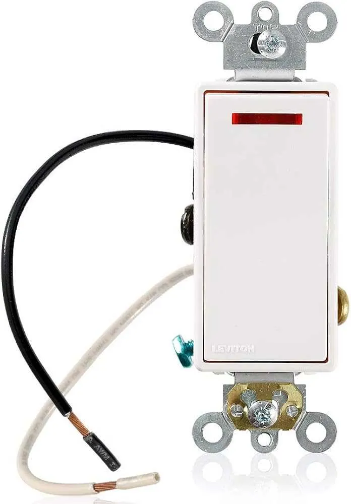
2. Identify the three terminals on the control device: common (usually black), traveler (typically brass), and ground (green). The illumination will be powered through a separate terminal, commonly marked as “L” or “illum.”
3. Connect the common terminal to the incoming hot wire (black). This wire should come directly from the power source.
4. Attach the traveler terminals to the two outgoing wires leading to the second control. These wires will control the light, allowing it to be toggled on or off from either device.
5. Ground the device by attaching the ground wire (bare or green) to the ground terminal of the control. If no ground wire is available, ensure that the junction box is grounded properly.
6. For illumination functionality, connect the “L” terminal to the neutral wire (white) in the electrical box. This is crucial for powering the light feature. The neutral wire completes the circuit for the illumination when the device is active.
7. Check for tight connections and ensure no exposed wiring is present, as this can cause a short or other electrical issues.
8. Mount the device securely into the electrical box and attach the faceplate. Make sure the screws are tight but not over-tightened to avoid damaging the housing.
9. Restore power at the breaker box, and test the control by toggling it. The light should turn on and off, and the indicator should be visible when the switch is in the on position.
10. If the light does not function as expected, verify the connections, especially the neutral wire, and check that the power supply is properly reaching the illumination terminal.
Following this step-by-step guide ensures a functional and safe setup for your electrical installation.
| Terminal | Connection |
|---|---|
| Common (Black) | Incoming Hot Wire (Black) |
| Traveler (Brass) | Outgoing Wires (to Second Control) |
| Ground (Green) | Ground Wire (Bare or Green) |
| Illumination Terminal (L) | Neutral Wire (White) |
Common Mistakes to Avoid When Installing a 3-Way Circuit with Illuminated Controls

1. Incorrect Terminal Connection: Always connect the traveler wires to the correct terminals on the device. Mixing up the terminals can prevent proper operation, causing the device to malfunction. Ensure the common terminal is linked to the power source, while the travelers connect to the other terminals accordingly.
2. Failure to Identify the Power Source: Not identifying the power source terminal can result in the device not receiving the necessary voltage. The power input should come from the panel, typically to the common terminal. Double-check the voltage at each terminal before making connections.
3. Not Using the Right Gauge for Conductors: Using an inadequate wire gauge for the load can lead to overheating or failure. For safety, use 14-gauge wire for standard circuits or consult code for heavier loads. Avoid undersized wire that could lead to shorts or fire hazards.
4. Inadequate Grounding: Always ensure proper grounding for all components. Failure to connect the grounding terminal properly increases the risk of electric shock or fire. The green screw or the grounding clip must be securely attached to the grounding wire, typically a bare copper or green wire.
5. Neglecting to Test Before Reassembling: After installation, never skip testing the circuit. Confirm the device operates correctly with both control points. If the control is non-functional, recheck the connections, especially the traveler wires, to ensure they are linked in the right configuration.
6. Overlooking the Neutral Wire: Some setups require a neutral wire connection to work properly. Ensure that all devices requiring a neutral are wired correctly, especially in systems that include an illuminated indicator. A missing neutral can prevent the indicator from lighting up or cause improper operation.
7. Poor Junction Box Placement: Make sure the junction box is placed in a location that allows for easy access to all terminals. Tight or overcrowded junction boxes can cause short circuits or prevent connections from being securely fastened. Give adequate space for wire manipulation during installation.
Troubleshooting Electrical Connection Problems in a Dual-Control Setup

Start by confirming that the power is off at the circuit breaker before you inspect the connections. Ensure all wires are securely attached to their respective terminals. A loose or disconnected wire can cause malfunction or failure to control the light from both locations.
Follow these steps to identify common issues:
- Check for power: Use a non-contact voltage tester to verify whether there is power in the box. If there is no power, check the breaker for tripped switches.
- Inspect terminal connections: Confirm that all conductors are tightly connected to the correct screws. Pay special attention to the traveler terminals, as loose connections here can cause intermittent operation.
- Examine the neutral wire: In some configurations, an improperly connected or missing neutral can cause the fixture to malfunction. Ensure the neutral wire is connected at both ends.
- Test the jumper wire: The jumper wire (or common terminal wire) should be connected securely. If it’s damaged or disconnected, the device may not work as expected.
- Check for faulty components: A defective part, like a damaged terminal or worn switch, can result in improper functioning. If all connections are good, replacing a suspect part may resolve the issue.
If troubleshooting does not resolve the issue, consult an electrician for further inspection, as there may be a deeper fault within the circuit.