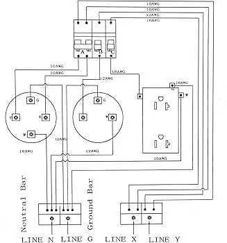
Ensure the safe installation of a 30A connection by following these key steps. Start by selecting the right wire gauge–use a 10 AWG copper or 8 AWG aluminum wire to handle the necessary load without overheating. Connect one wire to the “hot” terminal, usually marked in black or red, ensuring a secure grip. The neutral conductor should be attached to the corresponding silver terminal, while the ground wire goes to the green or bare terminal.
It’s essential to check local electrical codes and regulations before proceeding. An improper setup can lead to serious risks such as electrical fires. The distance between the power source and your RV is also a factor–make sure the wire is long enough to avoid tension but short enough to prevent unnecessary energy loss. Always use a proper weather-resistant casing for the wires to protect them from environmental damage.
Lastly, test the system before finalizing installation. A multimeter should be used to verify the voltage output and ground connection. After ensuring all connections are correct, securely fasten all components and check the wiring periodically to avoid wear and tear.
Electrical Setup for 30-Amp RV Connection
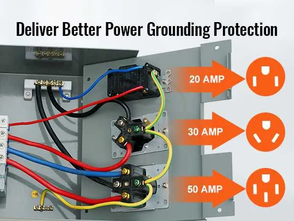
Ensure a 30A circuit breaker is installed to protect the system. Use a 10 AWG wire for the hot, neutral, and ground conductors. The red wire should carry the live current, the white wire serves as neutral, and the green or bare copper wire is used for grounding. The hot terminal of the receptacle connects to the red wire, while the neutral terminal is connected to the white wire. Ground the metal box and the receptacle with the green or bare copper wire.
At the panel, connect the red wire to the 30A breaker and the white wire to the neutral bus bar. Ground the system at the panel by attaching the green wire to the ground bus. Use locknuts to secure the box and ensure no loose connections. Verify each connection is tightly secured to avoid any electrical faults.
For the power supply to the RV, ensure the setup matches the vehicle’s requirements. Double-check all connections to guarantee correct polarity. Testing the system before use can help ensure safety and functionality, avoiding potential issues while on the road.
Understanding the Components of a 30 Amp RV Outlet Setup
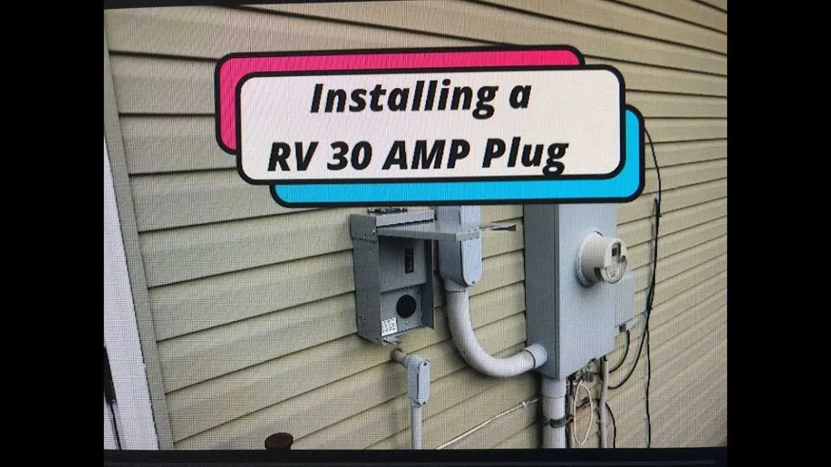
Ensure the correct use of a 30-amp circuit breaker designed for high-power applications, which should match the power demand of your vehicle. This breaker serves as a safety mechanism to prevent overloads, cutting off the flow of electricity if an excess load is detected.
The connector used to hook up the system must feature three prongs: one for the hot wire, one for the neutral wire, and one for the ground. Properly align each wire to avoid electrical faults and to meet National Electrical Code (NEC) standards.
The gauge of the cable you select is crucial. A 10 AWG wire is typically recommended to ensure safe current transmission without overheating, particularly over longer distances. Be mindful of wire quality, as it impacts conductivity and the longevity of the connection.
Grounding is essential in preventing electrical shocks. Ensure the ground wire is securely attached to the outlet box, following all safety protocols. The grounding system must be properly bonded with the main power panel to maintain safety throughout the setup.
Check the receptacle’s build and design. It should be weather-resistant and rated to withstand outdoor elements if the setup is exposed to external conditions. Make sure the prong openings are free from corrosion or wear to guarantee a solid, reliable connection each time.
Lastly, verify that all connections are tightened and free of any potential short-circuits. Loose connections can lead to overheating or sparks, creating a serious safety risk. Regular inspection and maintenance are key to ensuring a consistent, safe power supply.
Step-by-Step Guide to Wiring a 30 Amp RV Outlet Safely
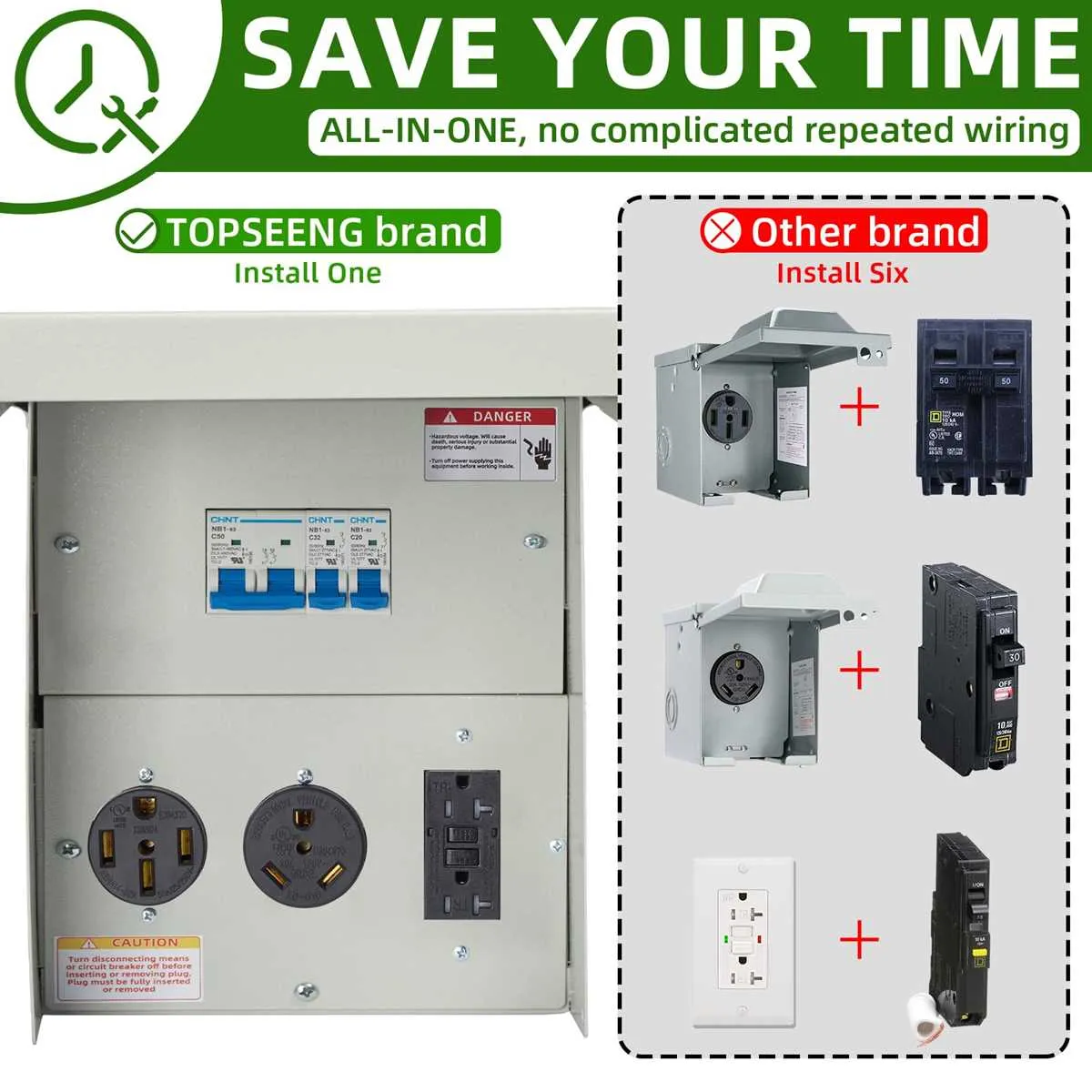
1. Turn off Power: Before beginning any electrical work, ensure the main circuit breaker is switched off. Confirm there is no voltage in the area using a tester to avoid accidents.
2. Select the Correct Cable: Use a three-wire 10/3 gauge copper or aluminum cable with grounding for safe current transmission. This ensures the wires can handle the high load without overheating.
3. Install the Receptacle Box: Choose a weatherproof box rated for outdoor use. Mount it securely, leaving enough room for the device and connectors. Ensure the box is positioned for easy access to the terminals.
4. Prepare the Cable: Strip about 6 inches of the outer insulation from the cable, exposing the three wires: black (hot), white (neutral), and green (ground). Be cautious not to damage the internal wires while stripping them.
5. Connect the Wires to the Receptacle: Attach the black (hot) wire to the brass screw, the white (neutral) wire to the silver screw, and the green (ground) wire to the green screw. Ensure each connection is tight to prevent any loose contacts, which can lead to arcing or overheating.
6. Attach the Cable to the Breaker Panel: Insert the black wire into the designated 30-amp breaker. Attach the white wire to the neutral bar and the green wire to the ground bus. Tighten the connections securely, ensuring there are no loose ends.
7. Check Connections: Before closing the box, double-check all connections for tightness and correct placement. Loose or misconnected wires can cause malfunction and pose a serious hazard.
8. Secure the Receptacle Cover: Once all connections are in place, attach the receptacle cover. Ensure it’s properly sealed, especially if installed outdoors, to prevent moisture from entering.
9. Test the Circuit: After ensuring all connections are secure, turn on the power at the breaker panel. Use a voltage tester to confirm the outlet is correctly energized and ready to use.
10. Inspect Regularly: Periodically check the installation for signs of wear or overheating. Ensure the receptacle remains securely mounted and that there are no exposed wires.
Common Mistakes to Avoid When Installing a 30A RV Connection
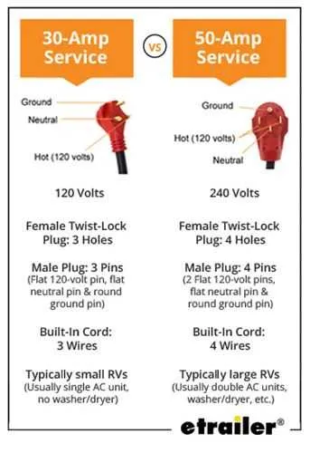
Ensure the circuit is rated appropriately for the required load. Using lower-rated wire or breakers can lead to overheating and fires.
- Incorrect wire gauge: Using 10 AWG wire instead of 6 AWG is a frequent error. For a 30A setup, 6 AWG copper or 4 AWG aluminum is required.
- Failing to connect ground properly: Never skip grounding the system. A poor ground connection can result in electric shocks and appliance damage.
- Improper breaker selection: Choose a breaker specifically designed for the system, with the correct interrupting capacity and trip characteristics. Generic breakers are often unreliable.
- Loose connections: Tighten every terminal connection to ensure safe operation. Loose connections cause arcing, which may lead to fire hazards.
- Excessive cable length: Longer wires increase resistance and can cause voltage drops. Always measure accurately before installation to keep wire lengths as short as possible.
Double-check the polarity of connections. Reversing the neutral and hot conductors can cause dangerous short circuits.
- Ignoring weatherproofing: Install covers and weather-resistant boxes to protect connections from moisture and outdoor elements.
- Inadequate box size: Ensure the electrical box is large enough to accommodate all wires and connections without strain. A cramped box can cause overheating.
- Neglecting to test: After installation, always test the system with a voltage tester to confirm the correct operation.
Finally, follow all local electrical codes and standards. Skipping regulatory checks might invalidate warranties or insurance policies.