
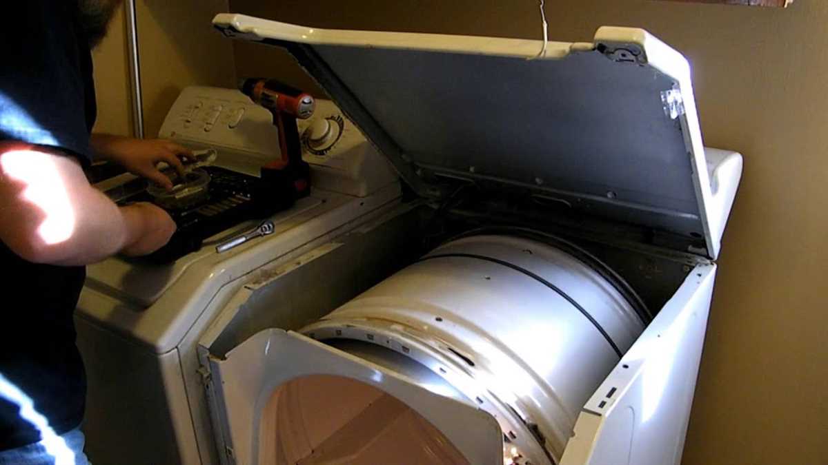
When it comes to repairing your Maytag dryer, having the right schematic drawings can make all the difference. These detailed diagrams provide a visual representation of the various components and wiring connections, allowing for easier troubleshooting and repairs. Whether you’re a seasoned DIY enthusiast or a professional technician, having access to Maytag dryer schematic drawings can save you time and effort in identifying and resolving issues with your appliance.
Maytag dryers are known for their durability and reliability, but like any other appliance, they can experience problems over time. From heating issues to electrical faults, understanding the inner workings of your dryer is crucial for effective troubleshooting. Schematic drawings provide a comprehensive overview of the dryer’s electrical system, heating elements, motor, and control panel, helping you pinpoint the exact component that needs attention.
Having access to Maytag dryer schematic drawings also enables you to perform repairs more efficiently. Instead of relying on guesswork or trial and error, you can follow the diagram to identify the faulty part and replace it. Additionally, these drawings can help you understand the proper wiring connections, ensuring that you reassemble the dryer correctly after making repairs. This can prevent further damage or safety hazards that may arise from incorrect reassembly.
Understanding Maytag Dryer Schematic Drawings
Schematic drawings are essential tools for understanding and troubleshooting Maytag dryers. These detailed diagrams provide a visual representation of the internal components and wiring connections of the dryer. By studying and interpreting these drawings, technicians and DIY enthusiasts can gain valuable insights into the functioning of the dryer and easily identify any potential issues.
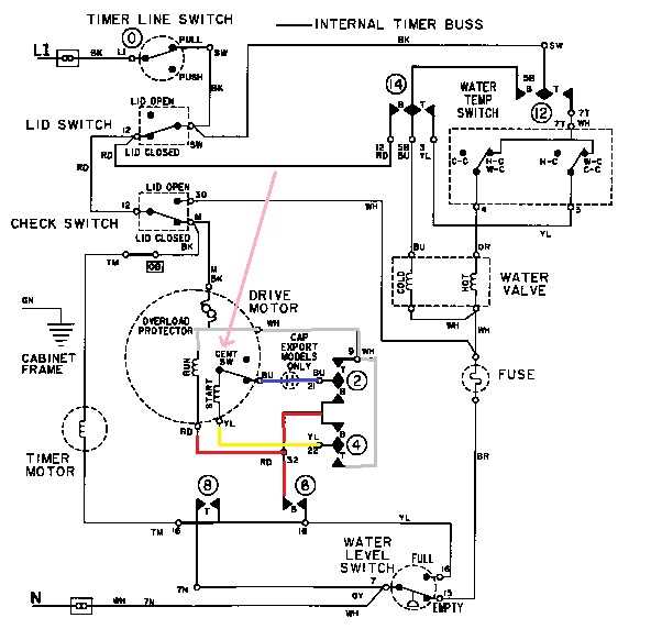
The Maytag dryer schematic drawings typically consist of various symbols and labels that represent specific parts and electrical connections. These symbols facilitate the understanding of how different components interact and work together within the dryer system. For example, a heating element may be represented by a zigzag line, while a motor might be depicted as a circle with a letter inside. The labels accompanying these symbols provide additional information about the specific part or connection.
One important aspect of understanding Maytag dryer schematic drawings is the ability to follow the electrical circuit. The drawings often include a wiring diagram that shows the path of the electrical current through the dryer. This information is crucial for identifying any potential issues with the electrical system, such as loose connections or faulty components. By tracing the circuit, technicians can easily pinpoint the source of the problem and make the necessary repairs.
Additionally, Maytag dryer schematic drawings may also include helpful annotations and callouts that provide further explanations or instructions. These annotations can be particularly beneficial for individuals who are not familiar with the inner workings of the dryer. They can help clarify the purpose of certain components or guide users through the steps of troubleshooting or repairing the dryer.
In summary, understanding Maytag dryer schematic drawings is essential for anyone involved in repairing or maintaining these appliances. These detailed diagrams provide a visual representation of the dryer’s internal components and electrical connections, allowing technicians and DIY enthusiasts to easily identify and troubleshoot any issues. By studying these drawings, individuals can gain a deeper understanding of how the dryer works and make accurate repairs and adjustments.
What Are Maytag Dryer Schematic Drawings?
If you’re a Maytag dryer owner or technician, you may have heard of schematic drawings. These drawings are an essential tool for understanding the electrical and mechanical components of your Maytag dryer. Essentially, schematic drawings are detailed diagrams that illustrate the circuitry and connections within the dryer’s system.
Schematic drawings provide a visual representation of the dryer’s internal components, allowing technicians to troubleshoot and repair any electrical or mechanical issues. They display the arrangement, connections, and functioning of various parts such as motors, switches, relays, and heating elements. Looking at a Maytag dryer schematic drawing, you can easily identify the path of electricity and how it flows through the different components.
These drawings are typically composed of symbols, lines, and labels, making them a universal language for technicians and experienced DIYers. Each part is depicted using standardized symbols, making it easier to interpret and understand the electrical and mechanical connections. Understanding these symbols is crucial for reading and interpreting the schematic drawings accurately.
Maytag dryer schematic drawings are often provided by the manufacturer and are part of the dryer’s service manual. They can be in the form of a two-dimensional diagram or a more detailed wiring diagram, depending on the complexity of the dryer’s system. These drawings are an invaluable resource for troubleshooting and diagnosing problems, as they provide a comprehensive overview of how the dryer functions and how the different components interact with one another.
In conclusion, Maytag dryer schematic drawings are detailed diagrams that illustrate the electrical and mechanical components of the dryer’s system. They provide a visual representation of how the different parts are connected and allow technicians to troubleshoot and repair any issues effectively. Whether you’re a Maytag dryer owner or a technician, understanding and correctly interpreting these schematic drawings is vital for maintaining and repairing the dryer.
Components of Maytag Dryer Schematic Drawings
Maytag dryers are complex appliances that require detailed schematics to understand their inner workings. Schematic drawings provide a visual representation of the different components and their connections within the dryer. These drawings are essential for technicians and DIYers who need to troubleshoot and repair the dryer.
1. Motor: The motor is one of the main components of a Maytag dryer. It is responsible for powering the drum and other moving parts of the dryer. The schematic drawing will show the motor’s connections to the different electrical components, such as the control board and the heating element.
2. Heating Element: The heating element is another crucial component of a Maytag dryer. It is responsible for generating the heat needed to dry the clothes. The schematic drawing will illustrate how the heating element is connected to the power supply, thermostat, and other related components.
3. Control Board: The control board is the brain of the Maytag dryer. It receives input from the user through the control panel and sends signals to various components to initiate and control the drying process. The schematic drawing will show the connections of the control board to other components, such as the motor, thermostat, and sensors.
4. Thermostat and Sensors: Maytag dryers have multiple thermostats and sensors to regulate the temperature and prevent overheating. The schematic drawing will indicate the placement and connections of these components, ensuring proper functionality and safety.
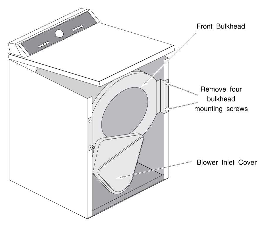
5. Drum and Belt: The drum and belt are responsible for rotating the clothes during the drying cycle. The schematic drawing will show how the drum is connected to the motor and how the belt is attached to the drum and motor pulley.
Understanding the components and their connections within Maytag dryer schematic drawings is crucial for troubleshooting and repairing the appliance. These drawings provide a valuable resource for technicians and DIYers, ensuring that the dryer functions properly and efficiently.
Reading and Interpreting Maytag Dryer Schematic Drawings
Maytag dryer schematic drawings are a crucial tool for understanding and troubleshooting the electrical and mechanical components of your Maytag dryer. These drawings provide a visual representation of the various parts and circuits within the dryer, allowing you to identify and fix any issues that may arise.
When reading Maytag dryer schematic drawings, it is important to have a basic understanding of electrical circuits and symbols. The drawings typically include symbols that represent different components such as motors, switches, heating elements, and sensors. By familiarizing yourself with these symbols, you can easily identify the different parts and their connections.
One important aspect of reading Maytag dryer schematic drawings is understanding the flow of electricity through the dryer. The drawings show the path that electrical current takes as it flows from the power source to the different components of the dryer. This information can help you pinpoint the cause of any electrical issues and determine the appropriate course of action.
Another important aspect of interpreting Maytag dryer schematic drawings is understanding the different circuits and how they interact with each other. For example, there may be separate circuits for the motor, heating element, and controls. By understanding the connections between these circuits, you can diagnose and troubleshoot problems more effectively.
In addition to electrical components, Maytag dryer schematic drawings also provide information about the mechanical parts of the dryer, such as the drum and belt system. These drawings can help you understand how these parts interact and how to properly assemble or disassemble them when necessary.
Overall, Maytag dryer schematic drawings are a valuable resource for anyone looking to understand and repair their Maytag dryer. By familiarizing yourself with the symbols and understanding the flow of electricity and the different circuits, you can effectively troubleshoot and fix any issues that may arise.
Common Symbols and Notations in Maytag Dryer Schematic Drawings
Schematic drawings are essential for understanding the electrical circuitry and components of a Maytag dryer. These drawings use a variety of symbols and notations to represent different elements and functions. Understanding these symbols can help troubleshoot and repair the dryer effectively.
Symbols for Electrical Components: Maytag dryer schematic drawings often include symbols for electrical components, such as resistors, capacitors, transformers, and switches. These symbols represent the presence and function of these components within the dryer’s circuitry. For example, a resistor may be represented by a zigzag line, a capacitor by two parallel lines, and a switch by a simple open or closed circuit symbol.
Notations for Connections: Schematic drawings also use notations to indicate how different components are connected. These notations can include lines or arrows that show the direction of current flow, dots or crosses to indicate junctions or connections, and labels or designations to identify specific points of connection. These notations help technicians trace the path of electrical current and identify potential issues or areas of interest in the circuitry.
Visual Representation of Mechanical Components: In addition to electrical symbols, schematic drawings may include visual representations of mechanical components such as belts, pulleys, motors, and heating elements. These visuals help technicians understand the physical layout and operation of these components within the dryer. For example, a motor may be represented by a circle with an M inside, and a heating element may be represented by a zigzag line inside a box.
Color-Coding and Line Styles: Some Maytag dryer schematic drawings use color-coding and different line styles to differentiate between different components or electrical connections. For example, wires carrying electrical current may be drawn in a solid black line, while wires representing ground connections may be drawn in green. This color-coding helps clarify the different functions and purposes of the various components and connections in the circuitry.
Key and Legend: To aid in the interpretation of schematic drawings, a key or legend is often included. This key provides an explanation of the different symbols, notations, and color-coding used in the drawings. It serves as a reference guide for technicians or individuals familiar with Maytag dryer schematics.
By familiarizing oneself with the common symbols and notations used in Maytag dryer schematic drawings, technicians and DIY enthusiasts can better understand the inner workings of the dryer and troubleshoot any electrical or mechanical issues with confidence.
Troubleshooting Using Maytag Dryer Schematic Drawings
Maytag dryers are known for their reliability and performance, but like any appliance, they can sometimes encounter issues. When troubleshooting a Maytag dryer, it can be helpful to refer to the schematic drawings that come with the appliance. These drawings provide a visual representation of the internal components and can help you identify potential problems and their solutions.
The first step in troubleshooting a Maytag dryer using schematic drawings is to locate the schematic diagram. It is typically found inside the dryer’s control panel or in the owner’s manual. Once you have access to the schematic, familiarize yourself with the different symbols and components depicted. This will make it easier for you to understand the electrical and mechanical connections of the dryer.
One common issue with Maytag dryers is a lack of heat. By referring to the schematic drawing, you can identify the heating element, thermostat, thermal fuse, and other relevant components. You can then use a multimeter to test these parts for continuity or resistance. If any of the components are faulty, they will need to be replaced. The schematic diagram will help you locate and remove the defective part.
Another common problem is a dryer that won’t start. By following the schematic drawing, you can trace the circuit and identify potential issues such as a faulty start switch, door switch, or thermal fuse. Again, using a multimeter can help you test these components for continuity or resistance. If any of the components are defective, they will need to be replaced to restore the dryer’s functionality.
Overall, Maytag dryer schematic drawings can be invaluable tools when troubleshooting and repairing your appliance. They provide a clear visual guide to the internal components and their connections. By following the schematic and using a multimeter, you can diagnose and fix common issues such as heating problems or problems with the dryer’s start mechanism.
Importance of Maytag Dryer Schematic Drawings
In the world of appliance repair, having access to accurate and detailed schematic drawings is crucial. Schematic drawings provide a visual representation of the electrical and mechanical components inside a Maytag dryer, allowing technicians to understand the inner workings of the appliance and troubleshoot any issues that may arise. These drawings serve as a map that guides technicians in diagnosing problems, identifying faulty parts, and performing repairs efficiently.
Accurate Troubleshooting: Maytag dryer schematic drawings help technicians efficiently troubleshoot common problems by providing a clear overview of the electrical system and the interaction between various components. By following the schematic, technicians can identify potential causes of malfunctions, such as faulty thermostats, clogged vents, or broken belts. This enables them to quickly pinpoint the issue and take the necessary steps to fix it, saving time and effort.
Repair Guidance: Schematic drawings provide detailed information about the wiring connections, voltage requirements, and component locations, aiding technicians in performing repairs accurately. They help prevent mistakes that could lead to further damage and ensure that the correct parts are replaced or repaired. By following the schematic, technicians can confidently navigate the complex network of wires and components, ensuring that the repaired Maytag dryer operates safely and efficiently.
Time and Cost Savings: Having access to Maytag dryer schematic drawings reduces the time and cost involved in repairing appliances. It eliminates the need for trial and error methods, as technicians can rely on the schematic to identify the root cause of a problem. This leads to quicker diagnoses and more efficient repairs, ultimately saving both time and money for both the technician and the customer.
In conclusion, Maytag dryer schematic drawings play a vital role in the world of appliance repair. They provide a visual guide that helps technicians accurately troubleshoot issues, perform repairs, and save time and cost. With these detailed drawings, technicians can confidently navigate and understand the complex inner workings of Maytag dryers, ensuring their optimal performance and customer satisfaction.