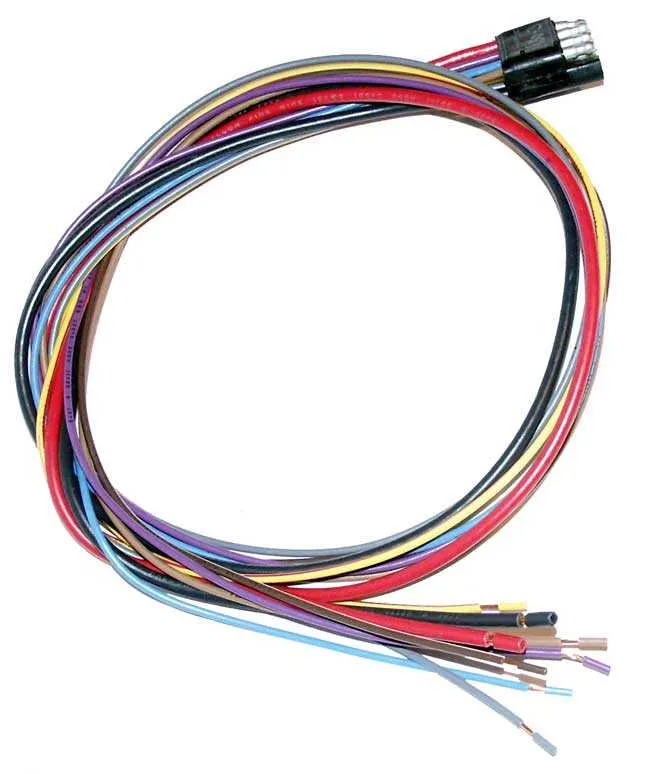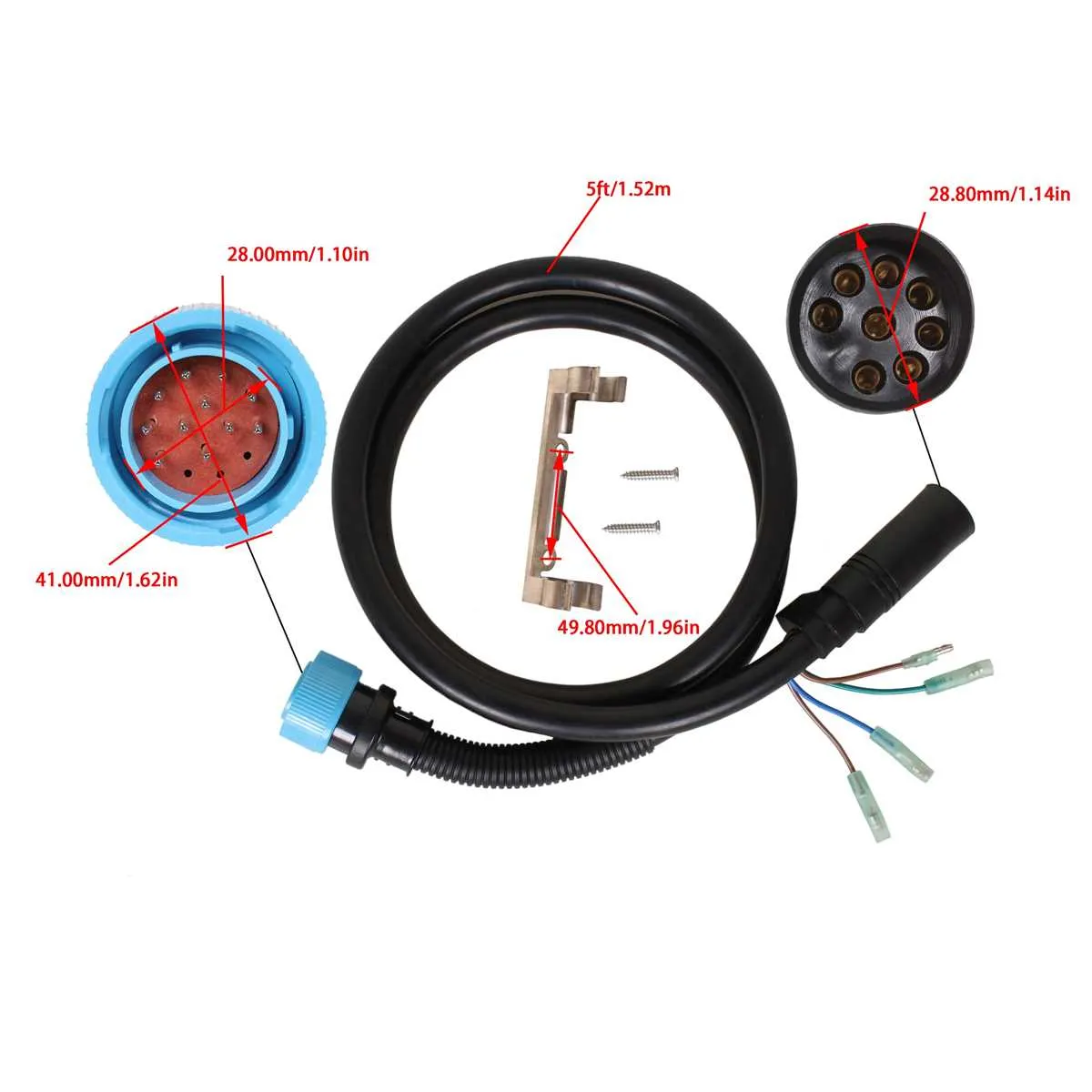
When dealing with an 8-terminal connector assembly, ensure you follow the correct pinout sequence for optimal performance. This connection setup is commonly used in various vehicle systems, and improper wiring can lead to malfunction or damage to sensitive components.
Start by identifying the function of each terminal within the unit. Most 8-terminal connectors serve specific roles such as power, ground, or signal transmission. It’s essential to trace each wire to its respective destination, ensuring they are connected properly to avoid any potential issues.
Use high-quality materials when replacing or modifying the cable setup. Poor-quality wires or incorrect gauge can lead to overheating or electrical failure. Pay attention to the manufacturer’s specifications regarding wire thickness and insulation standards.
Labeling each wire before making connections can save valuable time during installation or troubleshooting. This step will help prevent confusion, especially if the system needs to be repaired or upgraded in the future.
Finally, always double-check the continuity and grounding of each connection before powering up the system. A simple multimeter test will ensure that all terminals are functioning correctly and no shorts are present.
8-Pin Electrical Connector Setup Guide

For a successful setup of your 8-pin connector, follow these essential steps to ensure proper functioning and avoid common wiring errors:
- Step 1: Identify each terminal on the connector. Verify each one is correctly marked or labeled for its specific role–this will prevent any confusion during the installation process.
- Step 2: Begin by connecting the power source. The primary voltage input should be linked to the designated power terminal. Make sure the connection is secure, with no loose wires.
- Step 3: Next, connect the ground. The ground terminal must be firmly attached to the negative side of the power source. Ensure the wire used is of sufficient gauge to handle the current.
- Step 4: Connect the control signals. If your setup requires signal input, route these connections through the correct terminals to avoid short circuits or incorrect functionality.
- Step 5: For feedback loops, connect the feedback signal to its designated terminal. Double-check polarity to ensure the feedback system operates correctly.
- Step 6: Test each connection using a multimeter. This will verify there are no shorts or incorrect connections before powering up the system.
- Step 7: Once all connections are made and verified, securely fasten the connector and ensure it is firmly in place. Proper insulation and strain relief are essential for long-term durability.
By carefully following these steps, you’ll ensure a reliable and efficient system, minimizing the risk of malfunctions or damage to components.
Understanding the Pinout Configuration of the Mercury 8 Pin Connector

Ensure you connect each wire to the correct terminal for proper function. The configuration of the 8-terminal connector follows a specific order, which must be adhered to avoid system failure or malfunction. Start by identifying each of the positions based on the intended signal flow.
Terminal 1 typically serves as the ground, providing the common reference for the electrical system. This is usually marked clearly on the connector to prevent confusion. Double-check the ground connection for consistency.
Terminal 2 is used for the power input, providing the necessary voltage to the unit. The gauge of the wire connected here should be appropriate to handle the current demands without overheating.
Terminal 3 is designated for signal output, often responsible for relaying data or communication signals to other components. A stable connection is crucial for accurate data transmission.
Terminal 4 is sometimes reserved for an auxiliary signal, such as an emergency override or diagnostic input. Ensure this terminal is only connected to compatible systems to avoid interference.
Terminal 5 often carries a switchable power signal, typically controlled by an external relay. It’s important to verify the switch’s operation before making any permanent connections to ensure proper function when toggled.
Terminal 6 may serve as a feedback loop, allowing the system to send status information back to the control unit. Pay attention to the polarity here to avoid reverse signals that could lead to errors.
Terminal 7 is frequently used for communication protocols, such as serial or data bus interfaces. Compatibility with the receiving system is key to ensuring smooth interaction between components.
Terminal 8 is often used as a secondary ground or shield connection, designed to reduce electromagnetic interference. Ensure a solid connection to prevent noise from affecting the overall operation of the unit.
Carefully map each connection and verify continuity before powering up the system. Using the correct gauge wire for each terminal, depending on its role, is essential for maintaining safety and efficiency. Always use proper tools and testing equipment when making connections to prevent damage or poor functionality.
Step-by-Step Guide to Wiring the 8-Pin Connector
Begin by identifying the individual wires based on their color codes. Ensure you have a solid understanding of the function each wire performs within the system. Incorrect connections can cause malfunctions or damage components.
Start with connecting the power supply wire to the designated terminal. Double-check the voltage requirements for the device you are working with and verify that the power cable matches the appropriate gauge to prevent overheating.
Next, connect the ground wire securely to the grounding point. This will ensure proper electrical return and prevent erratic behavior. The ground connection should always be clean and free from corrosion.
For the signal wires, make sure to follow the exact order specified by the manufacturer. These are typically responsible for transmitting data or triggering specific actions in the system. Using the wrong pin for data transmission can lead to failures.
When connecting control wires, such as those responsible for activating a switch or motor, use connectors that ensure a tight and secure fit. Loose connections can result in intermittent operation or failure to respond.
If the system uses a relay, make sure the relay wires are connected in the correct sequence, especially the coil terminals and switch terminals. Verify the relay’s specifications to ensure the load it is managing matches the required parameters.
For the final connections, check each wire one last time for signs of wear or fraying. Insulate all exposed areas properly to prevent short circuits. Use high-quality electrical tape or heat shrink tubing for added durability.
Once all connections are secure, perform a test run to check for any issues. If the system operates correctly, the wiring job is complete. If issues arise, review the connections step by step to pinpoint the fault.
Common Electrical Issues and Troubleshooting Tips
1. Check for Loose Connections – Ensure that all connectors are securely plugged in. Loose or improperly connected terminals are a common cause of power interruptions or erratic behavior. Inspect for any corrosion on the contact points and clean as necessary using a contact cleaner or fine sandpaper.
2. Inspect for Wire Damage – Visually inspect cables for fraying, cuts, or exposed wiring. These can cause shorts or open circuits. If any wire appears damaged, it should be replaced immediately to prevent further issues.
3. Verify Grounding – A poor ground connection is often the culprit behind electrical malfunctions. Make sure the ground wire is firmly connected to a clean metal surface, free from rust or debris. Re-tighten any loose ground connections to ensure proper functionality.
4. Test for Continuity – Use a multimeter to check for continuity in each wire. A lack of continuity may indicate a broken wire or connection. This step is essential to verify that each circuit is complete and functional.
5. Inspect the Fuses – Check for any blown fuses that may be preventing power from reaching certain components. If a fuse has blown, replace it with one of the correct rating. Avoid using a fuse with a higher rating, as this could cause further damage to your system.
6. Examine the Relays – Relays can sometimes fail due to internal component issues. Test the relays using a multimeter to ensure they are switching correctly. Replace any faulty relays to restore normal operation.
7. Troubleshoot Voltage Drops – Measure voltage at different points along the circuit. A significant voltage drop may indicate a poor connection or a defective component. Identifying these points can help isolate the problem more quickly.
8. Corrosion Prevention – Corrosion can build up over time, especially on exposed metal parts. Use a dielectric grease to coat connectors and terminals to prevent moisture buildup and subsequent corrosion.
9. Verify Proper Component Installation – Ensure that each part is correctly installed according to the manufacturer’s specifications. Incorrect installation can lead to malfunctions or electrical overloads, so always double-check positioning and orientation.