If you are working with vehicles or machinery that rely on compressed gas to halt movement, understanding the key components and their connections is essential. The pneumatic stopping mechanism consists of several parts that ensure controlled deceleration. Knowing how air pressure interacts with the mechanism can help in troubleshooting, maintenance, and efficient operation.
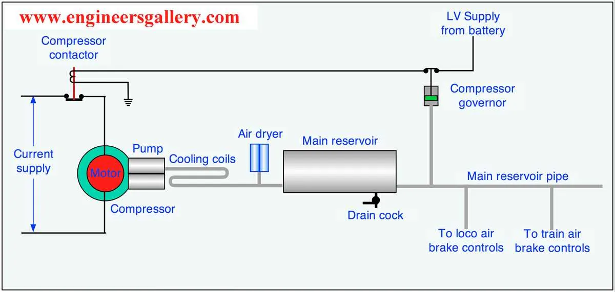
The primary components involved include the compressor, storage reservoir, and valves. The compressor generates the required pressure, which is stored in the reservoir for later use. Proper storage and pressure management are crucial for optimal functionality and safety. The valves play a critical role in releasing the pressurized air at the right moment to activate the stopping action.
To maintain efficiency, it’s vital to ensure the correct setup of these elements. Regular inspections for leaks and pressure irregularities are necessary to prevent failures. Additionally, understanding the flow of gas and the role of each part will aid in faster repairs and longer-lasting performance.
Understanding the Pneumatic Control Circuit

The most crucial aspect of a pneumatic control circuit is the proper layout of components to ensure reliable operation. Start by ensuring the compressor generates sufficient pressure and the reservoirs maintain optimal storage. Regulators should be placed near the reservoir to control pressure before it enters the main lines.
Valves play a pivotal role in controlling the flow of compressed air. A well-configured valve setup will allow precise control over activation and release sequences. Ensure that each valve is correctly sized and placed to avoid unnecessary delays or inefficiencies in response time.
For optimal performance, include moisture traps and filters along the supply line. These help in removing contaminants and moisture, which could damage the components or reduce the longevity of the entire circuit. Place them close to the main distribution points to maximize their effectiveness.
The layout of piping is also crucial; minimize sharp bends to reduce friction losses. Use appropriately sized piping to prevent flow restrictions, ensuring smooth transitions between components.
Lastly, integrate sensors and monitoring devices to track pressure levels and alert operators to potential issues. Regular maintenance of each component is essential to avoid system failures.
Understanding the Components of an Air Brake System

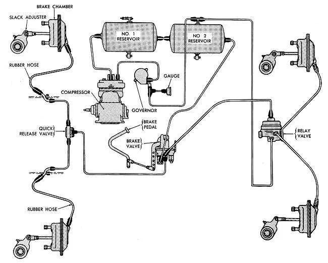
Ensure you have a clear understanding of the primary components involved in the operation of this type of stopping mechanism. The key parts include the compressor, which pressurizes air to operate the entire setup. A reservoir stores this compressed air, keeping it available for use in moments of need. The valves control the release of pressure, allowing for precise control over the vehicle’s stopping power.
Another crucial element is the control valve, which receives input from the driver and regulates air pressure based on braking demand. The relay valve ensures that the pressure gets delivered to the necessary sections of the setup with minimal delay. The actuating mechanism typically involves pistons or diaphragms that convert the pressure into mechanical force to halt motion.
Inspect and maintain each of these parts regularly to ensure optimal function. Failure in any of them, such as leaks or malfunctioning valves, can result in delayed responses or complete system failure, posing serious safety risks.
How Pressure Is Controlled in the Circuit
The regulation of pressure within the circuit is managed by a combination of valves and regulators that ensure precise distribution. The primary device responsible for controlling pressure is the governor, which adjusts the compressor’s output based on demand. When the pressure reaches a predetermined threshold, the governor stops the compressor from supplying additional force until the levels drop, maintaining equilibrium.
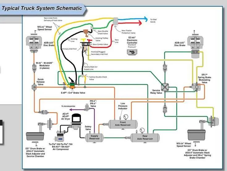
Additionally, a relay valve is used to modulate the flow, enabling quick response to changes in demand. This valve directs the flow to the necessary components while preventing excessive force buildup. If the pressure exceeds safe limits, safety valves are activated, releasing excess force and protecting the components from potential damage.
For fine control, pressure modulation is achieved using modulators that adjust the force based on real-time conditions, ensuring consistent performance across various load conditions. This setup guarantees that the pressure remains within optimal working ranges, providing reliable performance under diverse operational environments.
Common Troubleshooting Steps for Pneumatic Failure Issues

Start by verifying the pressure levels in the primary reservoir. Low pressure indicates a potential leak or malfunction in the compressor or its components.
- Inspect the compressor for signs of wear or failure. Ensure it is engaging properly and producing the expected pressure.
- Examine hoses and connections for leaks. Use soapy water or a leak detection tool to identify any escaping air.
- Check the valves for obstructions or damage. Ensure they open and close smoothly and that no debris has caused blockages.
- Test the control valves and actuators for responsiveness. If any part fails to actuate correctly, replace it immediately.
If issues persist, inspect the exhaust port for proper ventilation and check for any moisture buildup that may affect component performance.
- Examine the pressure relief valve to ensure it is functioning properly and not venting prematurely.
- Confirm that all seals are intact and show no signs of degradation that could cause improper sealing.
- Check for any signs of contamination in the compressor’s intake or filters, which can hinder airflow.
Once the components are inspected and issues resolved, recheck the overall pressure to ensure it is within operating range before proceeding with testing under load conditions.