To ensure a safe and efficient connection to the electrical grid, follow the recommended sequence for integrating your power measurement system with the household wiring. Proper installation is critical for both functionality and safety. First, confirm that the incoming line voltage matches the system’s specifications, and always check for any grounding issues before proceeding.
Ensure that all components are installed according to local regulations and utility requirements. A clear understanding of the load center connections and phase distribution is crucial for accurate power readings. For systems with multiple circuits, make sure to correctly route the conductors to avoid overloading any single path.
Use high-quality connectors for all terminals, as subpar materials can cause overheating and eventual system failure. It is also advisable to double-check the connections for tightness before powering up the system. An organized approach can prevent future problems and make troubleshooting easier should the need arise.
Lastly, remember that any modifications or upgrades to the system should only be performed by a licensed electrician, ensuring compliance with both safety standards and operational efficiency.
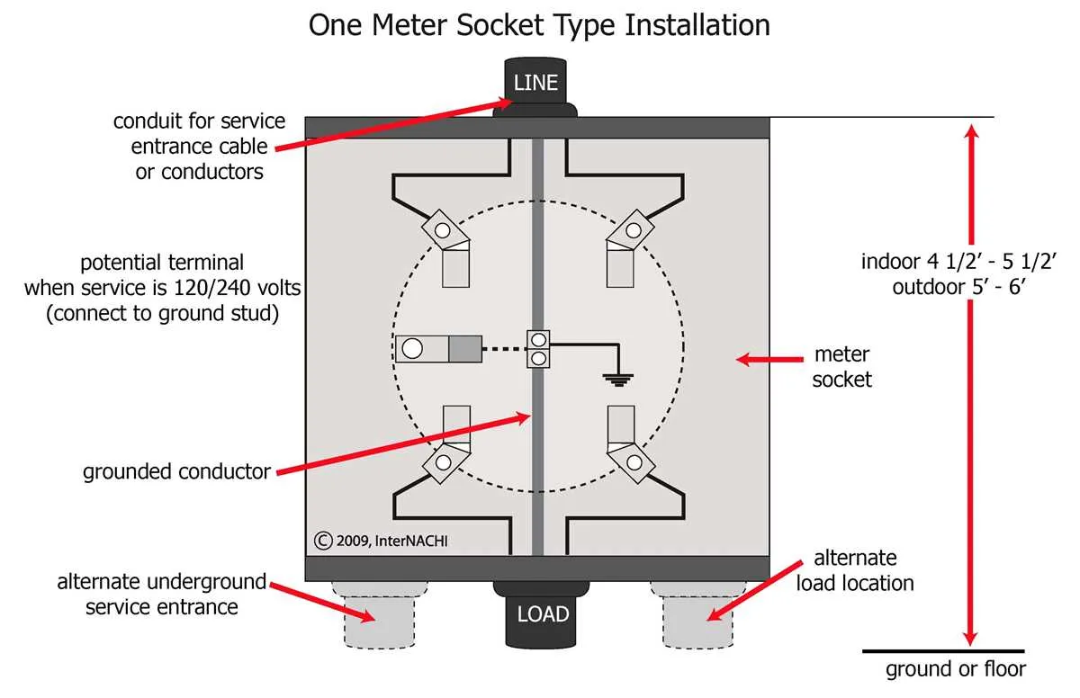
Electrical Service Connection Layout
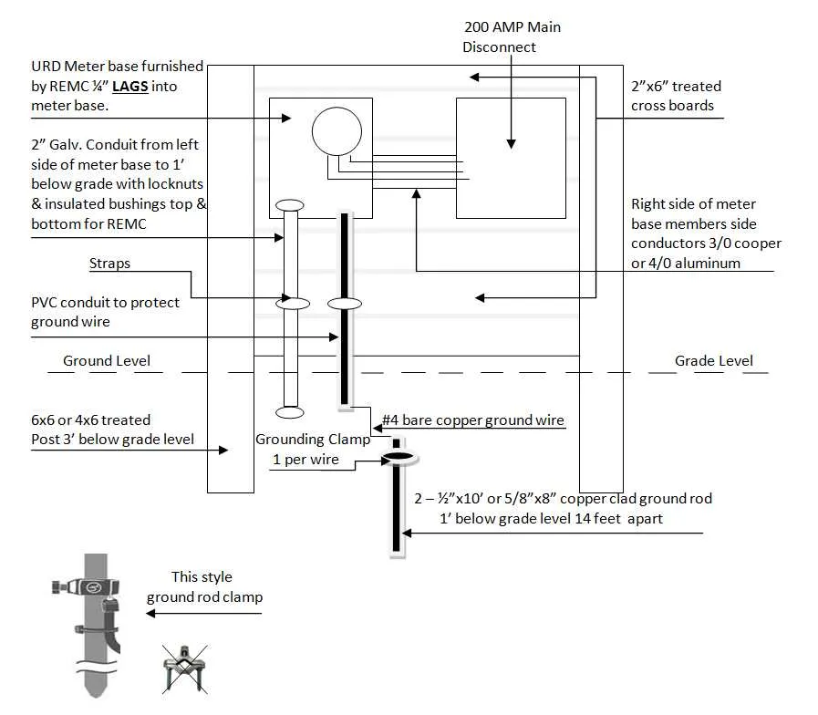
Ensure proper alignment of all components before beginning installation. The neutral and hot conductors must connect securely to their respective terminals. Verify that all connections are tightly secured to prevent arcing or overheating. Grounding should be performed according to local codes and standards, typically using a separate ground rod or system. Double-check the continuity of the ground path to ensure safety.
When positioning the conductors, make sure the power input lines are placed in such a way that they avoid any sharp bends, which can cause insulation damage or increase resistance. Use appropriate gauge wires to match the load and prevent overheating. Each connection point should be inspected for signs of wear or damage prior to energizing the system.
The main service conductors should enter from the top or bottom as per design specifications, ensuring the alignment follows manufacturer guidelines. If using a system with bypass switches, confirm they are in the off position during the installation process to prevent unintentional contact with live wires.
After installation, test all connections using a multimeter to ensure proper voltage levels. If any irregularities are detected, recheck the connections and ensure all components are compatible with the load specifications. Never exceed the recommended amperage rating for the system components.
Understanding the Main Components in an Electrical Connection Setup
Service entrance conductors are the primary cables delivering power from the utility to the distribution panel. They must be appropriately rated for the system’s voltage and current demands, and the size of these cables should match the maximum load capacity of the service. These wires connect directly to the incoming terminals at the power input point, often referred to as the “line” side.
Neutral bus bar serves as the return path for electric current. It is an essential part of the assembly that allows the balanced flow of power between the live and neutral wires. Ensure that the neutral connection is isolated from the ground to prevent potential safety hazards.
Grounding system ensures safety by providing a path for fault currents to return to the earth, reducing the risk of electric shocks. A proper grounding electrode system must be connected to the structure, and all metal parts of the system must be bonded to this ground to prevent dangerous electrical surges.
Load side terminals are where the power is distributed to the internal circuits of the building or structure. These terminals are connected to the distribution panel, directing electricity to various circuits that serve different parts of the property. Proper sizing and secure connections are critical to prevent overloads.
Service disconnect switch allows for quick interruption of power flow in case of emergency or for maintenance purposes. It must be easily accessible and capable of handling the maximum current that might flow through the system without causing any issues.
Overcurrent protection device is installed to prevent damage to the system and prevent fire hazards. This device automatically shuts off power if the current exceeds a safe level, acting as a safeguard for the entire setup.
Step-by-Step Guide to Connecting the Electrical Supply Unit for Residential Use
Before beginning, ensure you have all necessary tools and materials, including appropriate gauge wire, safety gear, and the correct mounting hardware for your location. Follow the steps carefully for a safe and efficient installation.
- Turn Off the Power: Disconnect the main power supply from the grid to avoid electrical hazards during installation.
- Mount the Unit: Securely position the electrical meter enclosure on the wall, ensuring it is level and within reach for future maintenance.
- Prepare the Input Cable: Strip the insulation from the incoming power cable, exposing the individual conductors. Ensure the cables are of the correct size for your local utility’s requirements.
- Connect the Neutral and Ground Wires: Attach the neutral conductor to the designated neutral terminal. Next, connect the ground wire to the grounding bar or designated terminal. Make sure these connections are tight and secure.
- Attach the Live Wires: Connect the live wires to the appropriate terminals. Typically, there will be two live terminals; connect each conductor according to the utility’s specifications for a balanced load.
- Verify Grounding: Ensure all grounding conductors are properly secured and connected to prevent electrical faults.
- Check Connections: Before closing the enclosure, double-check all wire connections for tightness and correctness. Ensure there is no exposed copper.
- Test the Unit: After securing the panel, restore the power supply. Monitor the unit for any signs of issues such as flickering lights or unusual noises. If all seems correct, your installation is complete.
Remember to follow all local electrical codes and consult with a licensed electrician if unsure about any steps. Proper installation ensures safety and compliance with utility regulations.
Common Electrical Issues and How to Troubleshoot Them

Check for Loose Connections – One of the most frequent problems is improper contact between components, causing flickering or total power loss. Inspect all terminals for tightness. Use a torque wrench to verify proper tightness for each connection, typically around 35-40 in-lbs for most components. Always turn off the power before inspecting or tightening any connections.
Incorrect Grounding – Improper grounding can lead to electrical surges or shock hazards. Ensure that the grounding system is connected to the correct bar and has a reliable path to earth. If the grounding wire is corroded or disconnected, replace or reconnect it as needed.
Overloaded Circuits – Excessive load on individual circuits can cause overheating or tripping of breakers. Check if any individual circuits are carrying more than their rated capacity, and redistribute loads if necessary. Upgrade breakers if the current ones are too small for the demand.
Faulty Breakers – Circuit breakers can degrade over time, leading to erratic or non-functional power cutoffs. Test the breakers by toggling them on and off to see if they properly disconnect under load. If they do not function correctly, replace them immediately.
Loose or Damaged Neutral Wire – A broken or improperly connected neutral wire often causes intermittent power disruptions or voltage imbalances. Verify that the neutral wire is properly attached to its respective terminal and not showing signs of wear or damage.
Corrosion on Electrical Contacts – Exposure to moisture can cause corrosion on electrical contacts, leading to overheating or short circuits. Inspect all components for signs of rust or buildup and clean contacts with an appropriate solution or replace the affected parts.
Voltage Imbalance – A discrepancy between the voltages in different phases can cause uneven load distribution and damage sensitive equipment. Use a multimeter to measure the voltage between each phase and neutral. If the readings differ by more than 10%, consult a licensed electrician for corrective action.