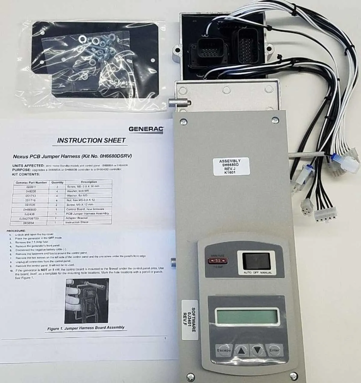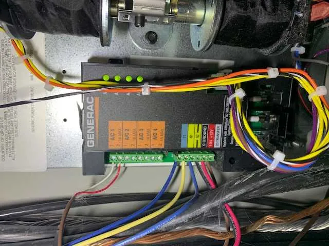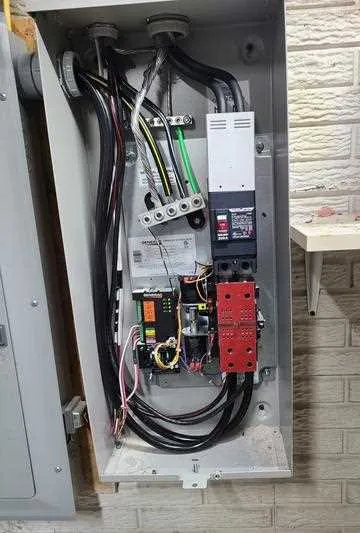
If you’re working with a backup power system, proper understanding of its electrical setup is crucial. Start by identifying the key components involved in the connection process, such as the control panel, battery, and circuit breakers. Ensure that all terminals are securely connected and the wiring follows the manufacturer’s guidelines. Any misconnection can lead to system failure or safety risks.
For safe operation, verify the grounding to prevent electrical hazards. The main power input and output wires should be connected to the correct terminals. Also, check that the voltage rating of each part matches the overall specifications. Use a multimeter to confirm correct voltage and ensure that the current flow is stable and within the safe operating range.
Ensure proper isolation between high-voltage and low-voltage components. This is especially important if the unit is intended to power different circuits or devices. Double-check the fuse ratings and replace any that are burnt out or damaged. The controller should be programmed for the specific settings of your system, allowing for safe transfer of power.
Lastly, consider the proper placement of cables. Avoid sharp bends or exposure to high temperatures, which can damage the wires over time. Regular maintenance checks are necessary to ensure that all connections remain secure and operational.
Electrical Circuit Layout for Generating Unit

Ensure all connections match the manufacturer’s recommended configuration to avoid damage or malfunctions. Follow these steps for proper setup:
- Power Leads – Verify the placement of power supply lines from the control panel to the unit’s main terminals. Double-check the gauges to ensure they meet required specifications.
- Grounding – Securely attach the grounding wire to the designated terminal. This step is crucial for the safety of the unit and prevents potential electrical hazards.
- Control Wiring – Connect the control circuitry based on the specific model. Make sure all relays and circuit breakers are correctly installed and that the switchgear functions as intended.
- Starting Mechanism – Confirm the starter motor’s connections are intact, with proper current flow from the start-up panel to the unit.
- Load Connections – Properly link the output leads to the transfer switch. Each connection should be tightened to avoid potential loose contacts that could lead to overheating or failure.
Use a multimeter to test voltage and continuity across each connection point, ensuring no disruptions or weak spots in the system. When unsure about any particular connection, consult the technical manual for additional specifications and diagrams tailored to your unit model.
How to Interpret the Generac Generator Wiring Diagram
Start by identifying the key components involved: the control panel, battery, and engine connections. These parts interact with each other through the electrical system, which is crucial for starting and maintaining operation. The symbols used to represent each component, such as circles for switches and squares for relays, are essential to understand for troubleshooting and maintenance.
Focus on the color codes and numbers associated with each wire. Typically, a red wire indicates a positive connection, while black represents negative. Use the labeled numbers to trace connections between components to ensure proper voltage flow.
Power Source Identification: Locate the power source section to identify the input and output terminals. These are critical for understanding how the unit receives power from the primary circuit and distributes it to different components.
Control Circuit: Pay attention to the control circuit symbols. The connections here are responsible for starting and stopping the engine. If the system is not starting correctly, check for continuity and any faulty connections within the control circuit.
Use a multimeter to check voltage and continuity across key connections to verify proper operation. Ensure all components match the labels provided on the chart, particularly the ground connections, to avoid electrical faults.
Test Points: Test the output at various terminals to ensure the system is running within the specified voltage range. Any discrepancies in voltage levels might indicate an issue in the circuit or a defective component.
Lastly, cross-reference the schematic with the actual unit. This is the best way to confirm that all components are installed correctly and that the power flow aligns with the manufacturer’s specifications.
Identifying Key Components in the Generac Generator Wiring Diagram
1. Power Supply Connections: Start by locating the main power inputs. These connections deliver electricity to the system, often marked with terminals like L1, L2, and Neutral. Pay attention to the specific color coding for each line to ensure proper voltage flow and avoid potential short circuits.
2. Control Panel Terminals: The control panel controls the operation of the system. Identify the terminals that link to the starter and the circuit breaker. Check for continuity to verify these connections are intact and provide proper control signals for activation.
3. Grounding System: Look for the ground symbol, typically connected to the frame of the unit. Proper grounding is crucial for safety, preventing electrical shock and ensuring the unit operates without interference from stray currents.
4. Battery Connections: Locate the battery terminals and verify the positive and negative connections. Ensure the battery is properly wired to the starter motor and other components for reliable power initiation.
5. Auxiliary Components: These include the fuel pump, exhaust system, and cooling fan. These components are vital for overall functionality, so ensure their connections are clearly marked and securely attached to the main power circuit.
6. Alternator and Voltage Regulator: Trace the path between the alternator and voltage regulator. Ensure that the wiring between these two parts is correctly placed to regulate power output and voltage levels.
7. Safety Mechanisms: Identify the fuses, relays, and other protective components. These ensure that the unit operates safely and can shut down in case of any faults. Make sure these parts are clearly connected and can activate in an emergency.
8. Sensors and Monitoring Devices: Sensors, such as oil pressure and temperature sensors, should be connected to the appropriate terminals. Confirm that these sensors are wired to the system’s monitoring unit, providing real-time performance feedback.
Troubleshooting Common Electrical Issues in Backup Power Systems

Check the battery connections first. Loose or corroded terminals often prevent the system from starting. Clean the terminals with a wire brush and tighten all connections to ensure proper contact.
If the unit fails to start despite a charged battery, inspect the fuse or circuit breaker. A blown fuse can prevent the electrical flow to the essential components. Replace any blown fuses and reset the circuit breakers if necessary.
Examine the control board for visible damage or burned-out components. Overheating or power surges can cause malfunctions. Replace damaged components with certified replacements to maintain the system’s integrity.
Test the voltage output at various points in the system. Use a multimeter to check for consistency. An irregular output may indicate a faulty regulator or a malfunctioning alternator. Both parts should be tested individually and replaced if needed.
Inspect the relay system. A stuck relay may prevent the automatic start-up or shut-off function. Apply a slight tap to the relay to see if it resets. If this method fails, replace the relay unit to restore normal operation.
Look for signs of wear or fraying in the power cables. Damaged insulation can lead to short circuits or power loss. Replacing damaged cables ensures uninterrupted power delivery.
Lastly, verify the grounding system. Inadequate grounding can lead to erratic behavior or electrical shocks. Ensure all ground rods are properly installed and connected to the system’s frame.