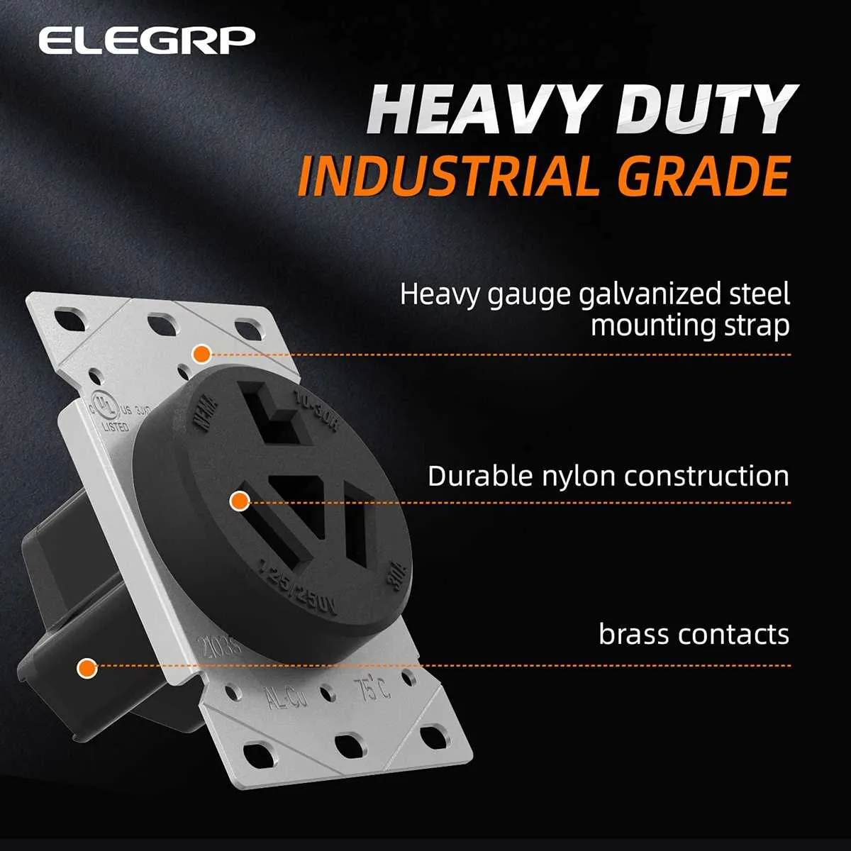
For optimal performance, it is essential to correctly identify the connections and their functions within the 10-pin system. Each pin in the setup corresponds to a specific function, and the correct pairing ensures efficient power distribution and operational reliability.
Ensure that the power supply is properly isolated before proceeding with the setup. The first pin typically represents the ground, followed by the phase connection and neutral. Verify that the wiring follows the recommended standards, as improper connections can lead to overheating or equipment malfunction.
To avoid potential issues, double-check each terminal’s voltage rating and current capacity. Use appropriate insulation and secure all connections with adequate tools to prevent accidental shorts or loose contacts. If uncertain about compatibility, consult the manufacturer’s guidelines for further details.
Properly configuring the connections guarantees that the system will function safely and effectively under various load conditions. Test the connections after installation, ensuring that all contacts are clean and securely tightened.
Electrical Connection Guide for 10-50R Receptacle

Ensure proper wiring of the 10-50R outlet by connecting the appropriate conductors to each terminal. The left terminal (usually marked “X”) is for the neutral wire, which should be white. The top terminal is for the live wire, typically black, and the bottom terminal is for the ground wire, which is green or bare copper. Confirm the wire gauge is compatible with the outlet’s rating to avoid overheating or faults.
To achieve a safe installation, verify the connection with a tester before use. The neutral wire should be at 0V, and the live should show the correct voltage, typically 240V. Use a dedicated circuit breaker rated appropriately for the system to prevent overloads. Tighten all connections securely to avoid any loose contacts, which could cause arcing and potential fire hazards.
If connecting to a 240V appliance, ensure the circuit is isolated and power is off before starting the installation. A grounded metal box is recommended to house the receptacle, which will enhance safety by providing an additional layer of protection. Always follow local electrical codes and standards for installation and maintenance of electrical outlets to ensure maximum safety and compliance.
Understanding the Nema 10 50r Socket Wiring
To ensure safe and correct installation, always confirm the power requirements of your devices before proceeding with the connection. A typical three-prong configuration involves a hot wire, a neutral wire, and a ground wire. The hot wire should be connected to the brass terminal, while the neutral wire connects to the silver terminal. The ground wire is linked to the green terminal.
When installing a receptacle, ensure the connections are tight and secure. Loose connections may lead to overheating or malfunction. For added safety, consider using a tester to verify the connections once completed. Also, always check that the voltage rating matches the device requirements to avoid damage or hazards.
If working with higher voltage systems, it’s crucial to use appropriately rated wire gauge. Using under-rated wire can lead to overheating and potential fires. Always follow local electrical codes and standards for your region.
Step-by-Step Instructions for Proper Connection
1. Disconnect Power Source: Before starting, ensure that the power supply is turned off to avoid electrical hazards. This is critical to safety when working with any high-voltage equipment.
2. Identify Terminal Labels: Verify the labels on the terminals to ensure proper attachment of each wire. Generally, the terminals will be clearly marked with symbols or letters, such as L (live), N (neutral), and ground. Double-check these markings to avoid errors.
3. Prepare Conductors: Cut the conductors to the appropriate length, leaving some slack for adjustments. Strip the insulation carefully to expose the copper wires without damaging them. Maintain clean and uniform wire ends for secure connections.
4. Connect Ground Wire: Attach the ground conductor to the designated ground terminal. This is usually a green or bare wire. Securely fasten it to the grounding screw or connection point.
5. Attach Live and Neutral Wires: Connect the live wire (typically black or red) to the terminal marked “L,” and the neutral wire (typically white) to the terminal marked “N.” Ensure each wire is properly inserted and tightened in its corresponding slot to avoid loose connections.
6. Tighten Terminal Screws: After all the wires are connected, use a screwdriver to tighten the terminal screws. Ensure each connection is firm to prevent accidental disconnections or short circuits.
7. Inspect and Test: Before restoring power, double-check the integrity of each connection. Verify that all wires are securely attached and that there is no visible damage. Turn on the power and test the system to ensure it functions correctly.
8. Final Safety Check: Once testing is complete, make sure all parts are safely enclosed and that no exposed conductors are visible. This will reduce the risk of shock or short-circuiting.
Common Issues and Troubleshooting Tips
Ensure proper grounding to avoid electrical shocks and prevent damage to equipment. If grounding is faulty, check for loose connections or broken wires in the circuit.
- Overheating: Excessive heat can cause system failure. Check for overload conditions and verify if the wiring gauge is adequate for the load.
- Power loss: If power is intermittent, inspect the connections for corrosion or wear. Tighten any loose terminals or replace any damaged components.
- Incorrect voltage: Measure voltage at key points in the system. If the voltage is fluctuating, ensure the power supply is stable and correctly matched with the requirements.
- Loose or damaged terminals: Check each terminal connection carefully. Re-tighten or replace any connectors that show signs of wear or looseness.
If troubleshooting does not resolve the issue, consider replacing the faulty component or seeking professional assistance. Always ensure that all components meet the electrical specifications required by your system.