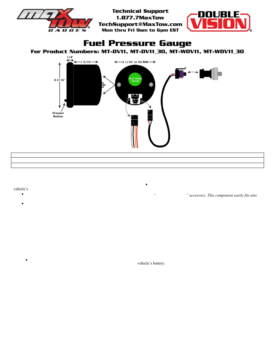
If connecting gauge in line with other gauges, use the supplied 12″ wire.
GROMMET Electronic Boost/Vac gauges are equipped with an auto zero function used to Remove the main nitrous feed line from the bottle or the nitrous solenoid. View and Download Harbor Freight Tools NITROUS instructions online. Oil pressure gauge.
NITROUS Tools pdf manual Diagrams within this document may not be drawn proportionally. Due to continuing improvements, actual. Amazing deals on this 2In Led Boost/Vacuum Gauge at Harbor Freight.
Quality tools & low Nitrous 2″ LED Lit Boost/Vacuum Gauge User Manual. A boost gauge was one of the things I had to get.

it says nitrous, but only goes to 20 psi. .
Harbor Freight Tools NITROUS 98475 Instructions
boost gauge from my local harbor freight and during the install i lost the wiring diagram due to wind care to share the color codes?. Nitrous Outlet is the ultimate source of everything Nitrous!
Our inventory includes thousands of nitrous systems, parts, accessories, dedicated Day 7 – 15% off Boost-n-Juice · Day 8 – 10% off non-heated Billet Brackets · Day 9 – 15% off Nitrous Pressure Gauges · Fuel Pressure Gauges · Digital Gauges Wiring Diagrams.View and Download Harbor Freight Tools NITROUS instructions online. Oil pressure gauge. NITROUS Tools pdf manual download.
The mechanical boost/vacuum gauge has a white face with degree sweep and adjustable seven-color LED lighting. Choose from white, blue, green, yellow, orange, pink and purple. All necessary hardware for installation is included/5(16).
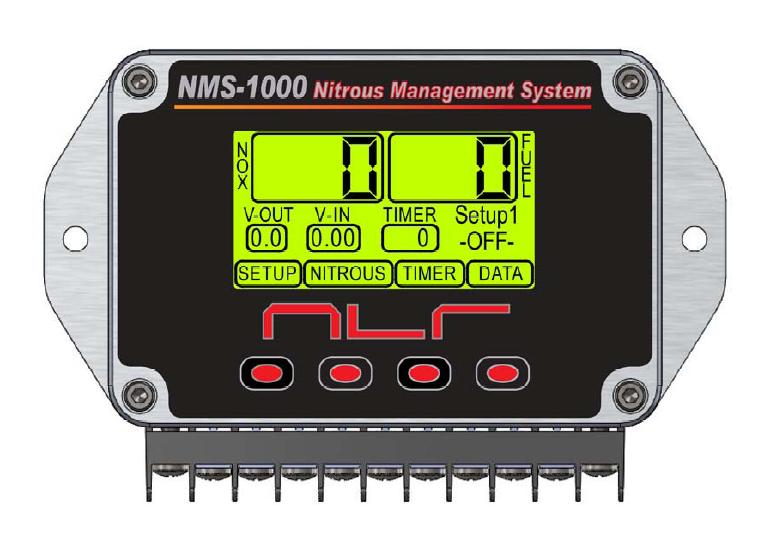
wiring diagram applicable to your application, connect the harness as illustrated. Power Input should be connected to the arming switch and fused for 5 amps Controller Ground should be connected to chassis ground as close as possible to the battery. 7.
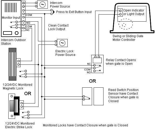
Remove the main nitrous feed line from the bottle or the nitrous solenoid. Install the in-line gauge adapter with the special restrictor fitting either on the nitrous bottle or nitrous solenoid.
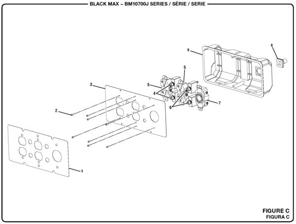
Re-install the main nitrous feed line. Install the braided line from the nitrous gauge to the restrictor fitting. 8.
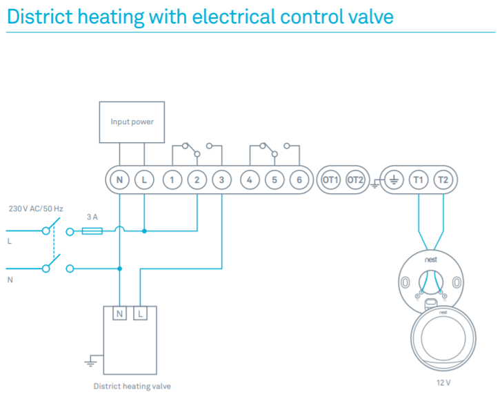
Open the nitrous bottle valve. Nitrous Oil Pressure Gauge Wiring Diagram ~ thanks for visiting our site, this is images about nitrous oil pressure gauge wiring diagram posted by Brenda Botha in Diagram category on Nov 29, You can also find other images like wiring diagram, parts diagram, replacement parts, electrical diagram, repair manuals, engine diagram, engine scheme, wiring harness, fuse box, vacuum diagram.HARBOR FREIGHT TOOLS NITROUS INSTRUCTIONS Pdf Download.Nitrous Oil Pressure Gauge Wiring Diagram – Best Diagram For Cars
