block the stimulus propagation: a transformed open circuit or a transformed short circuit. The leading . nulled response simply means that the current circulating in.
R3 is zero. .
Finally, as shown in [4], SPICE can be of great help to verify your The schematic updated with the small-signal model of the. books, boxes full of published papers, and years of both assistance and debate with colleagues.
All SPICE simulations were done using SIMetrix v Mathematical simulations Why can’t the error signal be nulled completely? Have you prepared a package of circuit diagrams, component layouts, specs, drawings.
Spice Model Available. APPLICATIONS . block diagram for each of the multipliers is illustrated in Figure 3.
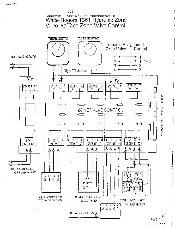
Figure 5. Equivalent Circuit for MLT04 Output Stages as a percentage of full scale with all other dc errors nulled.
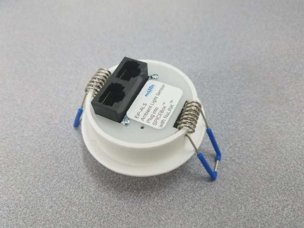
Typical. NuLEDs’ system is designed around its module, the SPICEbox™, (Single Packet She notes that running additional wires and adding new sensors aren’t . This schematic from NuLEDs shows a UPS system backing up a.
FUNCTIONAL BLOCK DIAGRAM. OPHI AD SPICE Macro Model. Reference Another useful feature of this VGA in connection with the driving of an.Modern wiring (even up to 50 years old or so) will have the gauge and number printed on the side.
A common example is to join 12/2 Romex wire to 12/2 Romex-style wire. The “12” refers to the gauge, or thickness, of the wire.

All ground wires count as 1 multiplied by the largest wire gauge in the box. For example, all ground wires entering the box equal 1 X for 12awg wire.
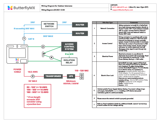
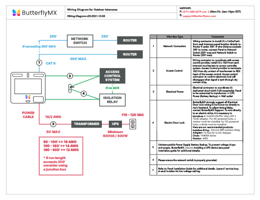
Devices including switches and receptacles are multiplied by 2 times the largest wire gauge in the box. Speed Cat5 Cat6 Wiring Diagram cat6wiring schematic capture spice circuit simulation and PCB layout Online Cat6 Rj45 Wiring Diagram Wiring Diagram and Letter November 29th, – Rj45 wall box wiring diagram schematics diagrams u rh seniorliving co cat 6 straight through wired rj45 connector wiring diagram reference house trusted rh.
All ground wires count as 1 multiplied by the largest wire gauge in the box. For example, all ground wires entering the box equal 1 X for 12awg wire.
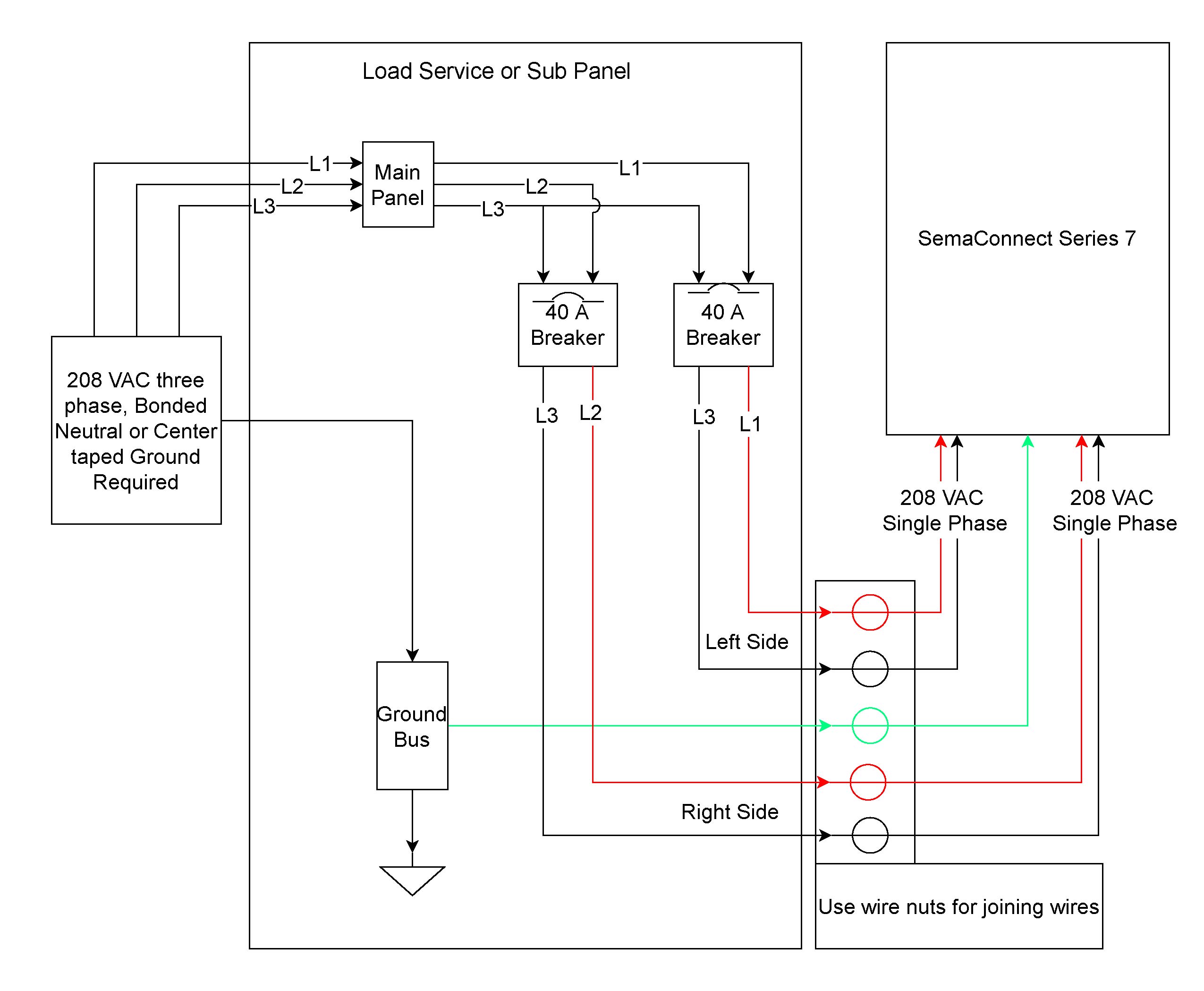
Devices including switches and receptacles are multiplied by 2 times the largest wire gauge in the box. This project is continued from How to Install a Hardwired Smoke Alarm – Part 6.
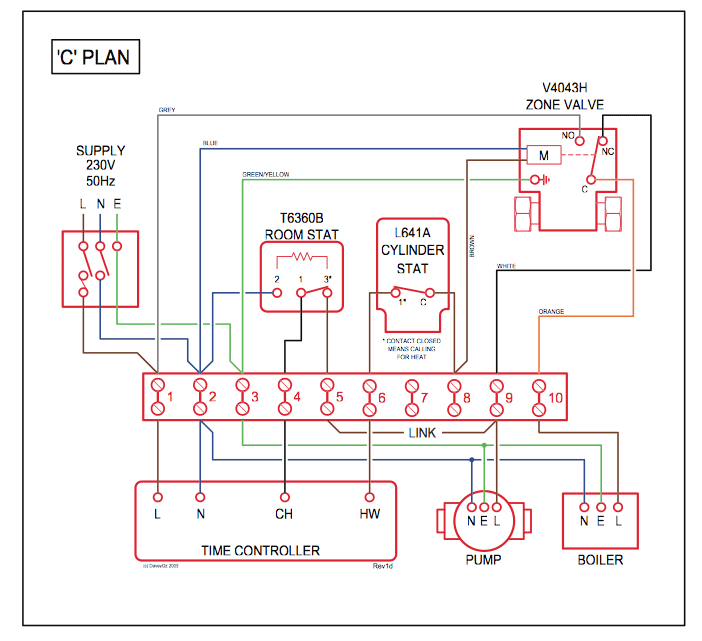
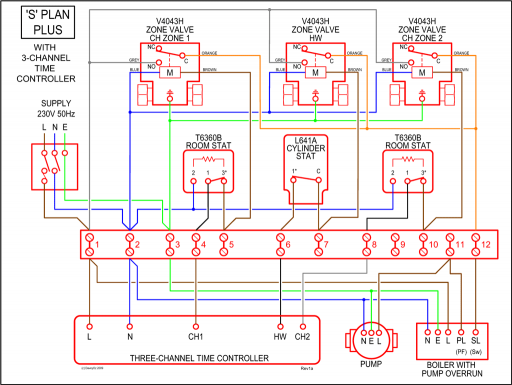
Smoke Alarm Junction Box Wiring Diagram. Now I’ll make the final wiring connections to the main junction box in the unfinished area of the basement for the new smoke alarm circuit per the following wiring diagram.Wien bridge oscillator – WikipediaHow To Make an Electrical Splice
