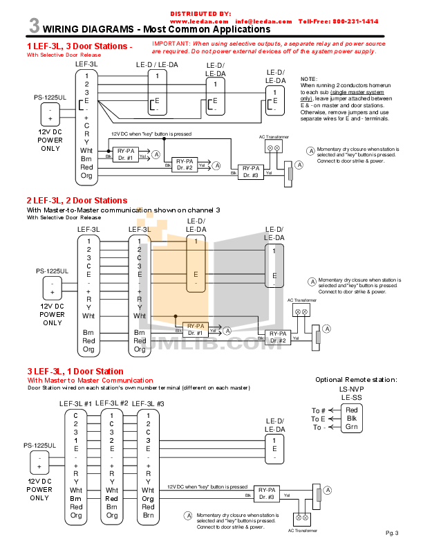
euro digital timer orbis timer wiring diagram euro din type digital timer manual din rail timer wiring diagram hager ege manual mem digital timer instructions. ORBIS. PRODUCT.
GUIDE. Optical Detector. Multisensor Detector.
Heat Detector How does the Orbis multisensor detector work?. 8 ..
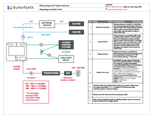
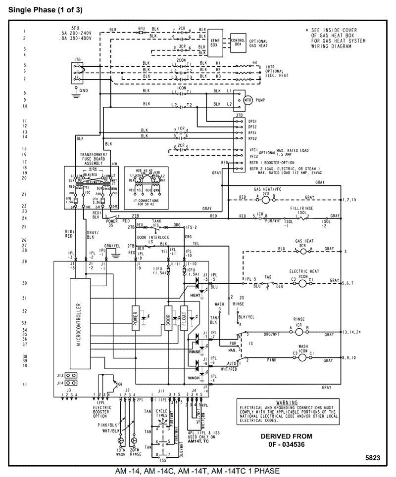
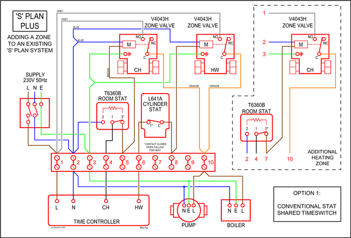
Base wiring diagram. PINS.
TIME SWITCH MINI T. OPERATING INSTRUCTIONS.
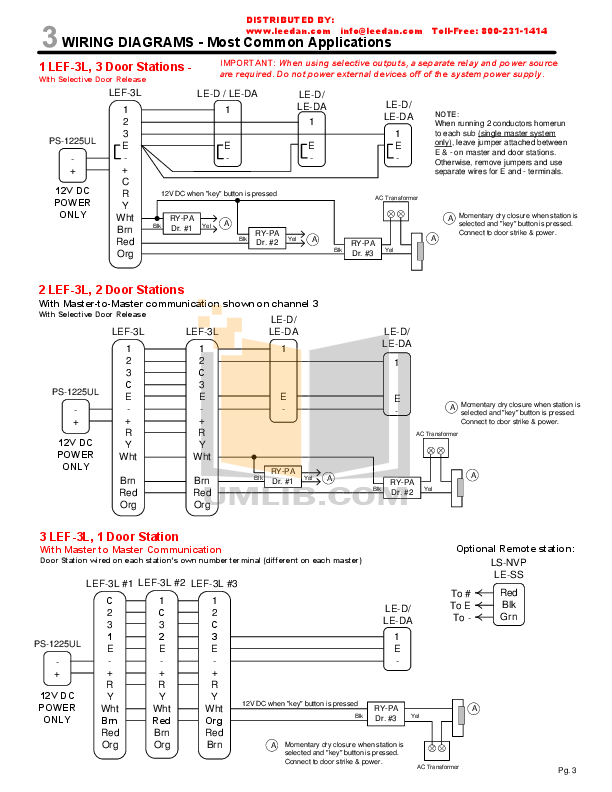
DESCRIPTION. Time switch with daily dial, captive pins and Faston type terminals for connection. It.
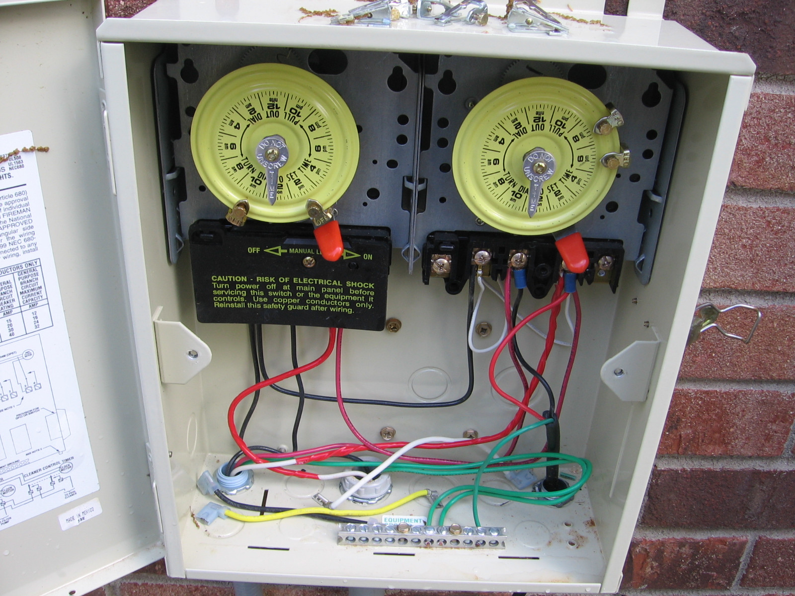
OK.. first check the breaker in the main electrical panel, make certain Intermatic Timer Motor WG / WG clock POOL FIX ON EBAY.
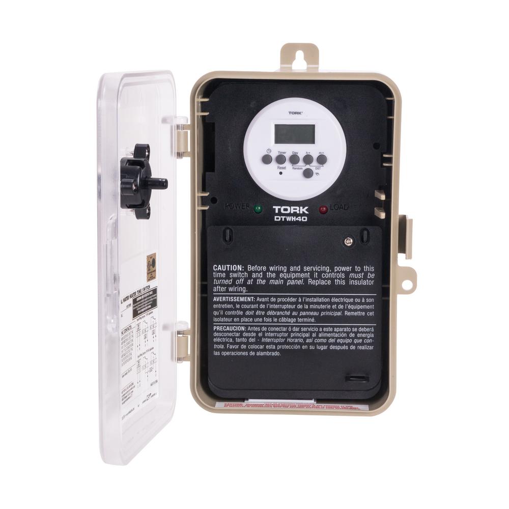
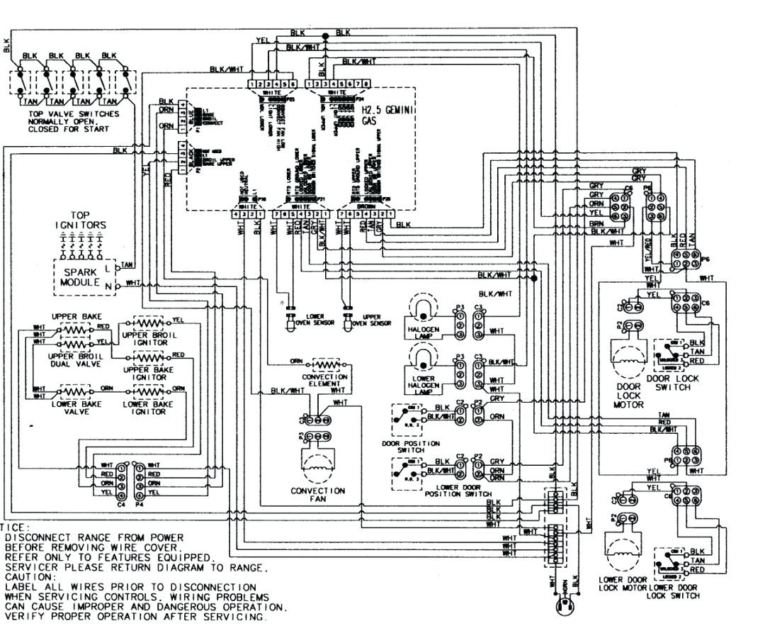
08/12/ Electrical diagrams: clock timer contactor ladder 4 wires. Esquemas eléctricos: interruptor crepuscular mural orbis domlux Esquemas Electricos.Interruptor horario analogico Analogue time switch ALPHA Cargas maximas recomendadas Maximum recommended load Conexion Dimensiones exteriores Wiring diagram Overall dimensions Accesorios Accessories available Codigo Code: Codigo Code: Codigo Code: Codigo Code: Codigo Code: Codigo Code: Codigo Code Sujeto a cambios tecnicos – information.
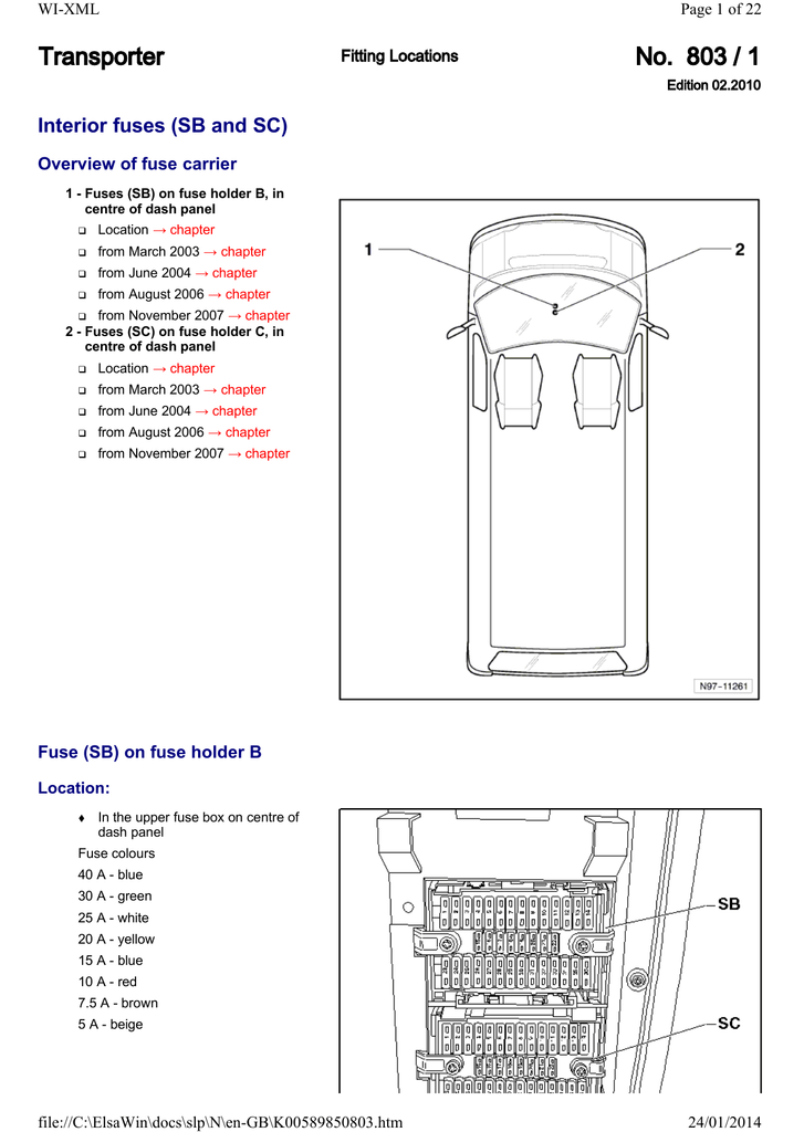
Dec 08, · staircase light timer switchThis just a basic how to do it video about how to wire a timer to give signal to energize equipment for example contactor’s and so on. And also a full explan mk.
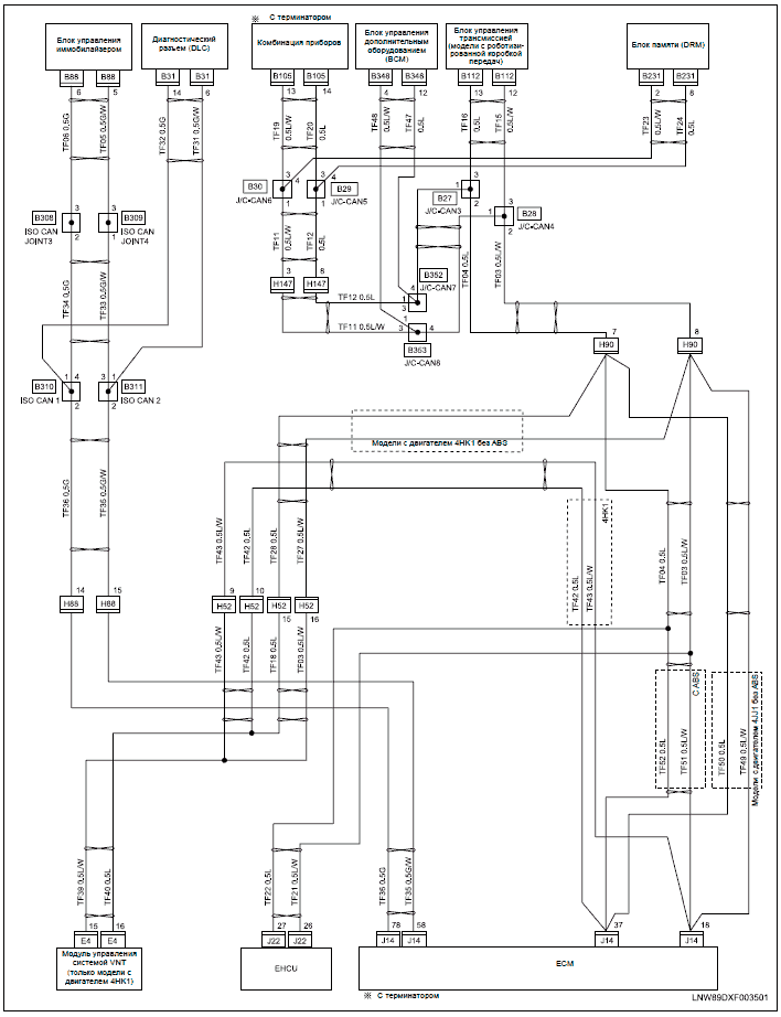
System Hardware Installation & BigComm Software User Instruction Manual Revision – December BigStuff3 Pro SEFI System Version – February 2 data logger and “Timer Enable” wire. Fore more information on how to wire and use these base system features go to the Boost section below.
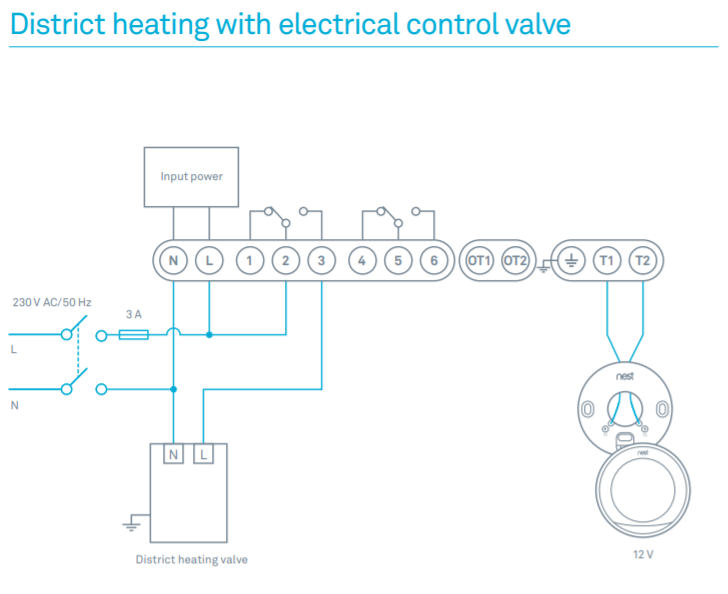
Injector Wire Harness BigStuff. Orbis Detector Label “XX” Apollo Detector Label L2 L1 Out L1 In L2 L1 Out L1 In L2 L1 Out L1 In “XX” Rev. P/N 6 Wiring Diagram for Input/Output Unit FR Note: If you require the Aux Battery to be charged by the Main Battery supply then fit D1charging diode (IN ) as per below.
Smart Switch Programmable Timer. When wiring the valves, use wire nuts and grease caps. The wire nuts create a secure connection between wires and the grease caps will ensure a waterproof seal.
Water getting into the wiring often damages the solenoids beyond repair, so this small investment will prevent extra expense and hassle.Orbis inca pool pump timer manual – FixyaAnalog time switch – UNO D, UNO QRD – ORBIS TECNOLOGÍA ELÉCTRICA