
Have you ever wished to have control over the lighting in your home or office without having to constantly adjust the settings? Well, you’re in luck! The Pir Override Switch is a revolutionary device that allows you to easily control your lighting with just a flip of a switch.
But what exactly is a Pir Override Switch? This device is essentially a switch that works in combination with a motion sensor, also known as a Passive Infrared (PIR) sensor. The motion sensor detects any movement in its range and triggers the lighting system to turn on. However, with the Pir Override Switch, you have the ability to manually override the motion sensor and control the lighting according to your preference.
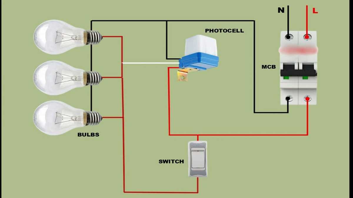
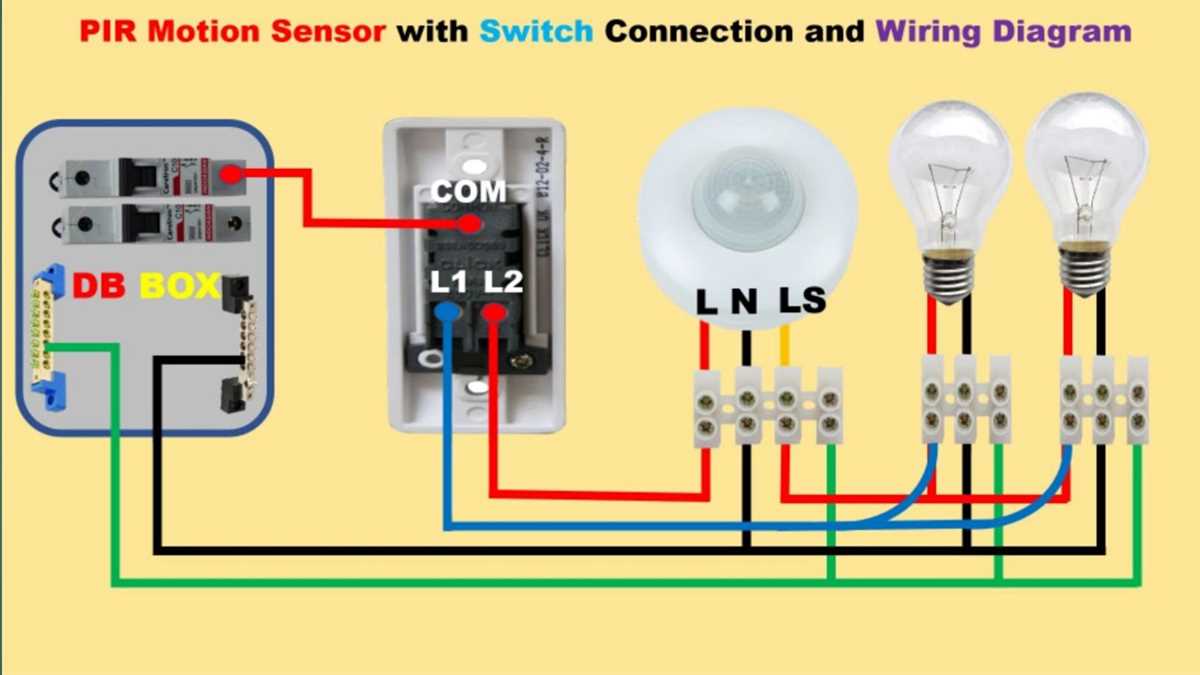
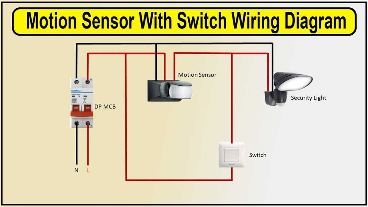
Now let’s dive deeper into the wiring diagram of the Pir Override Switch. There are three main components involved: the PIR sensor, the Pir Override Switch itself, and the lighting system. The wiring diagram shows the connections between these components, making it easier for you to understand how they work together.
Overview of PIR override switch
PIR override switch is a device used to manually control the operation of a passive infrared (PIR) sensor. The PIR sensor is commonly used in security systems to detect motion and trigger alarms or lighting. However, there are situations where it may be necessary or desirable to temporarily disable or override the PIR sensor, for example, when performing maintenance or adjusting the sensor’s sensitivity.
The PIR override switch allows the user to easily override the PIR sensor by turning it off or on as needed. It typically consists of a simple ON/OFF switch that interrupts the power supply to the sensor. When the switch is in the OFF position, the PIR sensor is disabled and will not detect motion. When the switch is in the ON position, the PIR sensor is enabled and will resume normal operation.
Installing a PIR override switch is a straightforward process. It involves disconnecting the power supply to the PIR sensor and connecting it to the override switch instead. The switch should be placed in a convenient location for easy access. It is important to ensure that the switch is properly rated for the power requirements of the PIR sensor to avoid any safety hazards.
By providing a manual override for the PIR sensor, the PIR override switch offers flexibility and convenience in controlling the operation of the sensor. It allows users to easily disable or enable the sensor as needed, without the need for complicated adjustments or programming. This can be particularly useful in situations where temporary overrides are required, such as during events or gatherings, or when the sensor’s operation needs to be controlled manually for any reason.
Understanding the basic components

When it comes to understanding the wiring diagram of a pir override switch, it is important to have a clear understanding of the basic components involved. These components play a crucial role in the operation and functionality of the switch, allowing it to override the passive infrared (PIR) sensor and provide manual control over the lighting system.
1. PIR Sensor
The PIR sensor, also known as a motion sensor, is a key component of the pir override switch. It detects movement by detecting changes in infrared radiation within its range. When motion is detected, it sends a signal to the switch, which triggers the lighting system to turn on. In normal circumstances, the PIR sensor controls the lighting system automatically, but with the pir override switch, the manual control can be enabled.
2. Override Switch
The override switch is the main control component of the pir override switch. It allows the user to manually override the automatic operation of the PIR sensor and take control of the lighting system. When the switch is in the “on” position, it disables the PIR sensor, allowing the lighting system to stay on regardless of motion detection. When the switch is in the “off” position, it restores the automatic operation of the PIR sensor, turning off the lights when no motion is detected for a certain period of time.
3. Wiring Connections
The pir override switch wiring diagram illustrates how the components are interconnected to create the desired functionality. It typically involves connecting the PIR sensor, override switch, and lighting system in a certain configuration. The specific wiring setup may vary depending on the switch and sensor model, but generally, it involves connecting the live and neutral wires of the power supply, as well as the wires for the PIR sensor, override switch, and lighting system.
Wiring the PIR Override Switch
Installing a PIR (Passive Infrared) override switch can provide added control and flexibility to your PIR lighting system. By wiring a switch in parallel with the PIR sensor, you can manually turn the lights on or off, overriding the motion detection function. This can be useful in situations where you want to keep the lights on for an extended period of time or when you need consistent lighting regardless of movement in the area.
To wire the PIR override switch, you will need a few key components: the PIR sensor, the override switch, a power source, and the lighting fixture. The wiring diagram will depend on the specific model and brand of your PIR sensor and switch, so it’s important to refer to the manufacturer’s instructions for the correct wiring connections.
Generally, the wiring process involves connecting the power source to the PIR sensor, and then branching off to the override switch and the lighting fixture. The exact configuration may differ, but typically you will need to connect the live (hot) wire and the neutral wire from the power source to the corresponding input terminals on the PIR sensor. The output terminals of the PIR sensor should be connected to the override switch, and then from the switch to the lighting fixture.
It’s important to ensure that the correct wiring connections are made to avoid any potential electrical hazards. Make sure to turn off the power supply before starting the wiring process, and use proper wire connectors to securely fasten the wires together. Test the system after installation to ensure that the override function is working as expected. If you are not confident with your electrical wiring skills, it is recommended to consult a licensed electrician for assistance.
Connecting the PIR Sensor
The PIR sensor, which stands for Passive Infrared Sensor, is a commonly used device in security systems and automatic lighting applications. It detects infrared radiation emitted by humans and animals and is an essential component for motion detection. To connect the PIR sensor to a circuit or system, several steps must be followed.
Step 1: Power Supply Connection
The first step is to connect the power supply to the PIR sensor. The sensor usually requires a power supply voltage within a specific range, which is typically mentioned in the datasheet. Ensure that the power supply voltage matches the requirements of the PIR sensor. Connect the positive terminal of the power supply to the positive terminal of the sensor and the negative terminal of the power supply to the negative terminal of the sensor.
Step 2: Output Connection
The PIR sensor provides an output signal that indicates motion detection. This output can be in the form of a voltage or a digital signal, depending on the sensor model. To use the output signal, it needs to be connected to the appropriate input of the circuit or system. Refer to the datasheet of the PIR sensor to identify the output pin and its specifications. Connect the output pin of the sensor to the corresponding input pin of the circuit or system, ensuring proper electrical connections.
Step 3: Adjusting Sensitivity and Delay
In some cases, the sensitivity and delay of the PIR sensor need to be adjusted to suit specific requirements. Usually, this is done using dedicated potentiometers or jumpers on the sensor board. Refer to the datasheet or user manual of the PIR sensor to understand the adjustment mechanism and make the necessary changes to achieve the desired sensitivity and delay settings.
By following these steps, the PIR sensor can be successfully connected and integrated into a circuit or system. It is essential to consult the datasheet or user manual of the specific sensor model being used to ensure accurate connections and proper adjustments. Additionally, it is crucial to consider any other requirements or specifications related to the overall application of the PIR sensor.
Configuring the Switch Settings
When configuring the switch settings for a PIR override switch, there are a few key steps to follow. First, you need to determine the purpose of the switch and the specific settings required for your application. This will typically involve consulting the wiring diagram provided by the manufacturer.
Next, you will need to locate the switch and wiring connections. This may involve removing a cover or accessing a control panel. Once you have access to the switch, you can begin configuring the settings.
- Start by setting the switch to the “off” position to ensure there is no power running through the circuit.
- Identify the different terminals or wires on the switch and determine their functions based on the wiring diagram.
- Connect the necessary wires to the appropriate terminals. This may involve twisting them together and securing with wire nuts or using terminal connectors.
- Double-check that all connections are secure and properly insulated to prevent any electrical hazards.
- Once the wiring is complete, you can move on to configuring any additional settings on the switch. This might include adjusting the sensitivity or time delay settings, depending on the specific requirements of your application.
Finally, test the switch to ensure it is functioning correctly. This can be done by applying power to the circuit and observing the switch’s response. If the switch is not activating or overriding the PIR sensor as intended, you may need to recheck your wiring connections or consult the manufacturer for further troubleshooting steps.
Testing and Troubleshooting
In order to ensure that your pir override switch is functioning correctly, there are several tests and troubleshooting steps you can take. Here are some tips to help you identify and fix any issues:
1. Check the Power Supply
Make sure that the power supply to the pir override switch is working properly. Check the circuit breaker to ensure that it is not tripped and verify that the switch is receiving the correct voltage.
2. Inspect the Wiring
Examine the wiring connections to ensure that they are secure and properly connected. Look for any loose or frayed wires, and make any necessary repairs or replacements.
3. Test the Switch
Use a multimeter to test the switch for proper operation. Ensure that the switch is making a good connection when activated, and that it is breaking the connection when released.
4. Check the Sensor
If the pir motion sensor is not working, check that it is properly positioned and aligned. Clean any dust or debris that may be affecting its performance, and adjust the sensitivity settings if necessary.
5. Review the Override Settings
Double-check the settings on the pir override switch to make sure that they are set correctly. Test the switch with different override settings to see if the issue lies with the configuration.
6. Consult the Manual or Manufacturer
If you are still experiencing issues, consult the user manual or contact the manufacturer for further guidance. They may be able to provide troubleshooting tips specific to your pir override switch model.
Remember to always prioritize safety when testing and troubleshooting electrical devices. If you are uncertain or uncomfortable with performing any of these steps, it is best to consult a qualified electrician.
By following these testing and troubleshooting steps, you should be able to identify and resolve any issues with your pir override switch. Ensuring that your switch is functioning properly is important for maintaining the security and convenience of your lighting system.