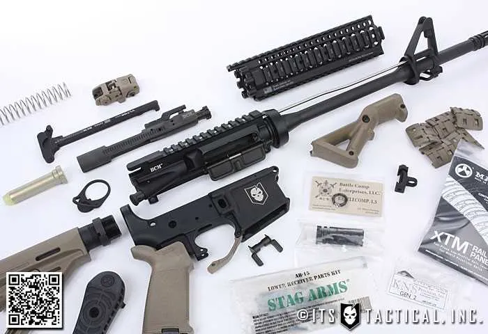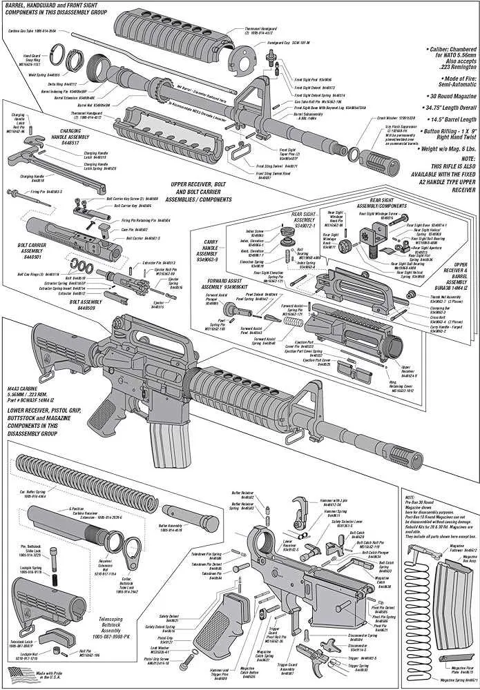
If you’re planning on assembling or maintaining a firearm, it’s crucial to have a detailed breakdown of its individual elements. Each piece plays a specific role in ensuring proper functionality and safety. Start by familiarizing yourself with the key components that make up the system, as understanding their interaction is essential for smooth operation.
Internals and Mechanisms are critical to the weapon’s performance. Pay special attention to the firing mechanism, the recoil system, and the trigger assembly. Each of these parts must be carefully examined for wear and tear to avoid malfunctions during use. Regular cleaning and lubrication of these areas will help maintain their longevity and reliability.
For anyone interested in precise assembly or troubleshooting, identifying each individual element and understanding its function can save time. Pay close attention to the upper and lower receivers, as they house several interrelated components that are essential for the weapon’s overall operation. Additionally, inspect the bolt carrier group regularly, ensuring that it moves smoothly within the receiver without resistance.
It is advisable to keep a detailed guide on hand when replacing or repairing any part. Always use parts that are specifically designed for your model to ensure optimal fit and performance.
Understanding the Key Components of the M&P 15 System
When assembling or maintaining the M&P 15, it’s essential to be familiar with its various parts to ensure proper function and safety. Here’s a breakdown of crucial elements of the firearm.
- Receiver: The main structure housing key components like the trigger mechanism, safety, and bolt carrier group. Ensure proper alignment and smooth operation when installing or cleaning.
- Barrel: Make sure the barrel is properly secured to the receiver with no obstruction. Any damage or dirt can affect accuracy and performance.
- Gas System: The gas block and tube work to cycle the action. Inspect these parts for blockages or signs of wear, as they directly affect cycling reliability.
- Buffer Assembly: The buffer and spring control the rearward motion of the bolt carrier group. Regularly check for proper functioning and replace the buffer if it shows any signs of damage.
- Bolt Carrier Group: This crucial unit should be regularly cleaned and lubricated to maintain reliable cycling. Ensure the firing pin, extractor, and other small components are not worn down.
- Charging Handle: A functional charging handle ensures smooth loading of rounds. It should be securely attached and show no signs of excessive wear or damage.
For optimal performance, always replace worn components with high-quality parts. Regular maintenance will extend the lifespan and reliability of your firearm. Keep a comprehensive list of essential components for reference when troubleshooting or upgrading your system.
How to Identify Key Components in the M&P 15 Diagram
Start by locating the upper receiver assembly, which houses the bolt carrier group and charging handle. This area is crucial for the rifle’s operation, as it controls cycling and feeding. Next, focus on the lower receiver, where the trigger mechanism, magazine well, and safety selector are positioned. Pay attention to the gas block and tube assembly, responsible for redirecting gas to cycle the bolt. The handguard section, typically located near the barrel, serves as the mounting point for accessories. Lastly, identify the buffer tube, which absorbs recoil and supports the stock assembly, ensuring stability during firing.
Step-by-Step Guide to Assembling M&P 15 Components

Start with securing the lower receiver and attaching the trigger assembly. Ensure the spring is properly aligned with the hammer and trigger mechanism. Once the trigger group is in place, secure it with the pins provided, ensuring they are fully seated to prevent movement during use.
Next, attach the buffer tube to the rear of the lower receiver. Tighten it firmly using a torque wrench to the manufacturer’s specified torque value to ensure proper alignment with the receiver extension. Check for any movement or play after tightening.
Move on to installing the gas tube. Align the gas block with the barrel, making sure the gas port is properly oriented. Slide the gas tube through the block and secure it with the set screws provided. Tighten evenly to avoid misalignment that could lead to malfunction.
Once the gas system is installed, proceed to the barrel assembly. Attach the barrel to the upper receiver and torque it according to the specified value. Ensure that the barrel nut is secured tightly to avoid any shifting during shooting. Verify that the barrel is correctly indexed with the upper receiver to ensure proper alignment.
Install the handguard by securing it to the barrel nut. If the model uses a free-floating handguard, ensure that it is properly seated and there are no gaps between it and the receiver. Double-check the attachment points to ensure there is no excessive movement.
Now, move on to the upper receiver assembly. Slide the bolt carrier group (BCG) into the upper receiver, ensuring it moves freely within the rail. Attach the charging handle to the receiver and check for smooth operation by pulling it back and releasing it several times.
Finalize the assembly by installing the front sight post or optic mount. Once the optic is securely attached, double-check all fasteners for tightness. Test the assembly for any wobble or movement in the components, ensuring that each part is securely in place before final use.
Common Troubleshooting Tips Using the M&P 15 Parts Diagram

Ensure proper assembly by verifying all components are securely installed, especially the recoil spring and buffer system. Incorrect placement can lead to feeding malfunctions or cycling issues.
Check the alignment of the gas block and gas tube. Any misalignment will result in insufficient gas pressure, causing the firearm to fail to cycle properly. Inspect for signs of wear or carbon buildup in the gas system that may impede function.
Inspect the trigger mechanism and safety features. If the trigger fails to reset or is sluggish, it may indicate an issue with the disconnector or trigger spring tension. Replace the spring if necessary.
Verify the magazine well for debris or wear. A dirty or damaged well can prevent the magazine from seating correctly, leading to feeding failures. Regular cleaning and lubrication are key to smooth operation.
Check for proper bolt carrier group function. If the group is not moving smoothly, it could be due to fouling, insufficient lubrication, or a worn-out cam pin. Clean and lubricate the group thoroughly, or replace the parts as needed.
| Issue | Potential Cause | Solution |
|---|---|---|
| Failure to Feed | Magazine misalignment or damaged magazine | Clean the magazine, check for damage, or replace if necessary |
| Failure to Cycle | Gas system misalignment or blockage | Inspect and clean the gas tube and block |
| Trigger Reset Failure | Faulty disconnector or trigger spring | Replace the disconnector or adjust the spring tension |
| Stiff Bolt Carrier | Excessive fouling or insufficient lubrication | Clean and lubricate the bolt carrier group |