
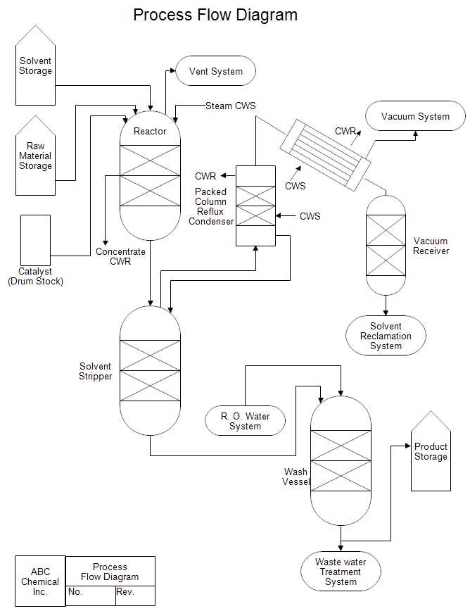
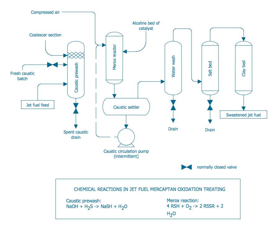
Process flow diagram (PFD) is a visual representation of a system or process in engineering. It shows the flow of equipment, materials, and information through the different stages of a process. PFDs are used by software engineers to understand and communicate the various steps involved in developing and implementing a software project.
Software engineering is the process of designing, coding, testing, and maintaining software systems. It involves a series of interconnected steps that are followed to create a software solution. PFDs are used in software engineering to visualize these steps and to analyze the flow of information and resources throughout the software development lifecycle.
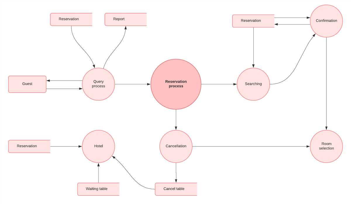
The PFDs used in software engineering typically include boxes or shapes to represent different tasks or activities, and arrows to indicate the flow of information or materials between these tasks. The tasks and activities may include requirements gathering, design, coding, testing, deployment, and maintenance. This visual representation helps software engineers to understand how the tasks are interconnected and how information and resources are transferred from one task to another.
Process flow diagram software engineering tools are used to create and update PFDs. These tools allow software engineers to easily draw and modify the diagrams and to add more details to them. They also provide features like collaboration and version control, which enable multiple engineers to work on the same diagram simultaneously and to track changes made to the diagram over time. Process flow diagram software engineering tools help to streamline the software development process and improve communication between team members.
Process Flow Diagram Software Engineering
The process flow diagram (PFD) is a visual representation of the steps involved in software engineering. It provides a high-level view of the software development process, allowing stakeholders to easily understand and communicate the flow of activities. The PFD is an essential tool for software engineers, project managers, and other team members to plan, track, and improve the software development process.
The PFD typically starts with the initial requirements gathering phase, where the software engineer interacts with the stakeholders to understand their needs and define the scope of the project. This is followed by the design phase, where the software engineer creates a detailed design of the software system, including the architecture, data structures, and algorithms. The next step is the implementation phase, where the software engineer writes the code and integrates various components to build the final software product.
Once the implementation is complete, the software goes through rigorous testing and quality assurance to ensure that it meets the specified requirements. This is followed by the deployment phase, where the software is released to the end-users or customers. Finally, the PFD includes a maintenance and support phase, where the software engineer provides ongoing support, bug fixes, and updates to the software.
The PFD is an effective visual tool that allows software engineers and other team members to identify bottlenecks, inefficiencies, and areas for improvement in the software development process. It helps in streamlining the workflow, optimizing resource allocation, and reducing development time and costs. By having a clear and standardized representation of the process, stakeholders can easily identify potential risks and dependencies, and make informed decisions to ensure the success of the software project.
In conclusion, the process flow diagram is an invaluable tool in software engineering, providing a clear and concise representation of the software development process. It enables effective communication, planning, and optimization of the process, resulting in higher quality software products and improved productivity.
Understanding Process Flow Diagrams
Process Flow Diagrams (PFDs) are an essential tool in software engineering. They provide a visual representation of how a process or system works, helping teams to understand and analyze complex workflows. PFDs use standardized symbols and arrows to show the flow of information, inputs, and outputs within a system.
Why are PFDs important?
PFDs are important because they help to simplify and clarify complex processes. They allow software engineers to identify bottlenecks, efficiency issues, and potential areas for improvement within a system. By visualizing the flow of activities, PFDs make it easier for teams to communicate and collaborate on software development projects.
What do PFD symbols represent?
There are several commonly used symbols in PFDs, each representing a different aspect of the process or system being analyzed. For example, rectangles typically represent processing steps, arrows represent the flow of information between steps, and diamonds represent decision points. These symbols can be combined and connected in different ways to create a comprehensive visual representation of the entire process.
Benefits of using PFDs in software engineering
- Improved understanding: PFDs make it easier for software engineers to understand how a system works, enabling them to identify issues and find solutions more effectively.
- Enhanced communication: PFDs serve as a common visual language that allows teams to communicate complex ideas and concepts more clearly.
- Increased efficiency: By analyzing the flow of activities and information, software engineers can identify areas for optimization and streamline the development process.
- Facilitated collaboration: PFDs provide a central point of reference for teams to collaborate and coordinate their efforts, reducing the risk of miscommunication or misunderstandings.
In conclusion, Process Flow Diagrams (PFDs) are an invaluable tool in software engineering. They help teams to understand, analyze, and optimize complex processes, improving efficiency and facilitating collaboration. By using standardized symbols and visual representations, PFDs provide a clear and concise way to communicate ideas and concepts within a development team.
Benefits of Process Flow Diagrams
Process flow diagrams (PFDs) are valuable tools in software engineering as they provide a visual representation of the steps involved in a process. These diagrams offer a wide range of benefits and are widely used in various industries. Some of the key advantages of using process flow diagrams include:
1. Clarity and Transparency: PFDs enable the clear and concise communication of complex processes. By presenting the steps, decisions, and inputs/outputs in a visual format, stakeholders can easily understand the flow and logic of the process. This clarity helps in avoiding confusion and misinterpretation, leading to more effective collaboration and decision-making.
2. Identification of Bottlenecks and Inefficiencies: By visually mapping out the process flow, PFDs help to identify bottlenecks, redundancies, and inefficiencies in the process. This allows software engineers to pinpoint areas that require optimization or improvement, leading to increased efficiency and productivity.
3. Standardization and Consistency: Process flow diagrams provide a standardized representation of a process, ensuring consistency in the execution of tasks. This helps in reducing errors, rework, and deviations from the established procedures. PFDs also serve as a reference for training new team members, ensuring that they follow the established process accurately.
4. Documentation and Knowledge Management: PFDs serve as documentation of the process, capturing essential details such as inputs, outputs, decision points, and dependencies. These diagrams help in preserving knowledge and can be used as a reference for future projects, audits, or process improvements.
5. Process Optimization and Continuous Improvement: By analyzing the process flow in PFDs, software engineers can identify areas that can be optimized or streamlined. This can lead to process improvements, cost savings, and enhanced customer satisfaction. PFDs also facilitate the implementation of continuous improvement initiatives by providing a baseline and enabling comparison of different versions of the process.
In conclusion, process flow diagrams are a valuable tool in software engineering, providing clarity, optimization opportunities, standardization, documentation, and continuous improvement capabilities. By utilizing PFDs, software engineers can streamline processes, improve productivity, and deliver high-quality software products.
Key Elements of a Process Flow Diagram
A process flow diagram (PFD) is a visual representation of the steps involved in a process or workflow. It allows engineers and software developers to analyze and optimize the flow of activities, identify bottlenecks, and improve overall efficiency. A well-designed PFD should include the following key elements:
1. Process Steps
The process steps are the individual tasks or activities that make up the overall process. They should be listed in sequential order and clearly labeled. Each step should have a unique identifier for easy reference and should be accompanied by a brief description of what it entails. This helps ensure that everyone involved in the process understands what needs to be done at each stage.
2. Decision Points
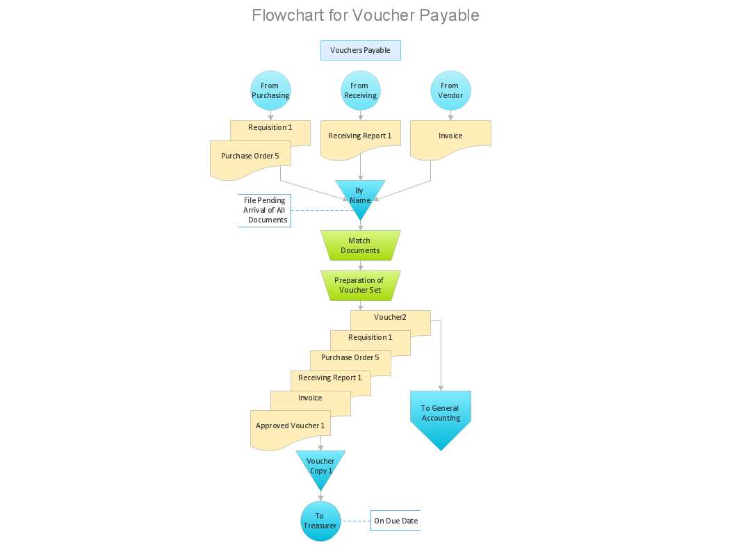
Decision points are critical junctures in the process where a choice needs to be made. This can include branching pathways or alternative routes based on certain conditions or criteria. Decision points should be clearly marked with labels and arrows indicating the possible outcomes or next steps. It is important to define the criteria or conditions that determine which pathway will be followed at each decision point.
3. Inputs and Outputs
Inputs and outputs are the materials, data, or information that are required or produced at each step of the process. It is important to clearly identify what inputs are needed to start a particular step and what outputs are generated upon completion. This helps ensure that all necessary resources are available and that the desired outcomes are achieved.
4. Flow Direction
Flow direction refers to the sequence in which the steps of the process are performed. It is represented by arrows connecting the various process steps and decision points. The flow direction should be clear and easy to follow, with the arrows indicating the logical order in which the activities are carried out. It is important to ensure that the flow direction is efficient and avoids unnecessary backtracking or repetition.
5. Timing and Dependencies
Timing and dependencies refer to the relationship between different steps in terms of their sequence and time requirements. Some steps may be dependent on the completion of others, while others may need to be performed concurrently or in a specific order. It is important to clearly indicate any dependencies or timing constraints in the process flow diagram to ensure that the workflow is realistic and achievable.
By including these key elements in a process flow diagram, software engineers and developers can gain a better understanding of the process and identify areas for improvement. A well-designed PFD can help streamline workflows, reduce errors, and increase overall productivity.
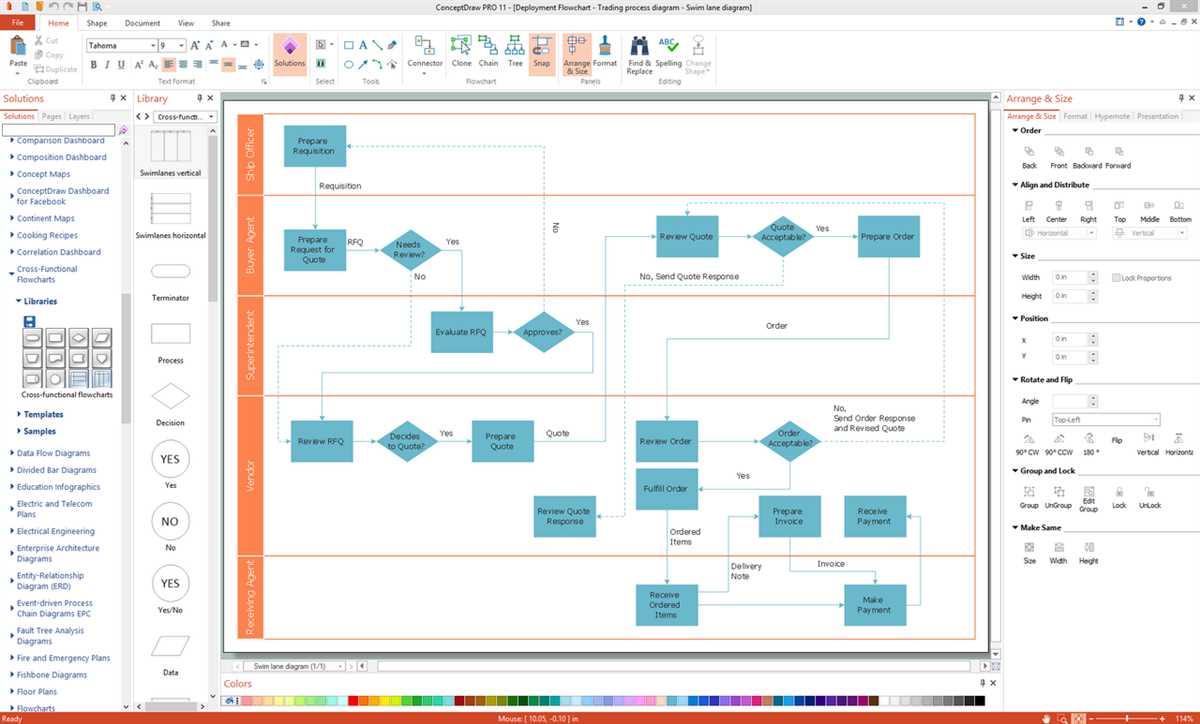
Types of Process Flow Diagram Software
Process flow diagram (PFD) software engineering is a crucial tool for designing and documenting workflows. There are various types of software available to create PFDs, each with its own features and capabilities. Let’s explore some of the common types of process flow diagram software used in the field of software engineering.
1. Drawing Software:
Drawing software, such as Microsoft Visio and Lucidchart, is widely used for creating process flow diagrams. These tools provide a wide range of symbols and shapes that can be used to visualize different components of a workflow. They also offer advanced features like drag-and-drop functionality, template libraries, and the ability to collaborate with team members in real-time.
2. Diagramming Software:
Diagramming software, like Gliffy and Creately, is another popular choice for creating process flow diagrams. These tools offer an intuitive interface that allows users to easily create and modify diagrams. They also provide a range of pre-designed templates for different industries, saving time and effort in designing a process flow diagram from scratch.
3. Business Process Management (BPM) Software:
BPM software, such as Bizagi and Tallyfy, goes beyond just creating process flow diagrams. These tools provide end-to-end process management solutions, helping organizations streamline their workflows and improve efficiency. With features like process modeling, automation, and reporting, BPM software offers a holistic approach to managing and optimizing business processes.
4. Project Management Software:
Project management software, such as Microsoft Project and Smartsheet, often includes features for creating process flow diagrams. These tools focus on project planning and execution, but also provide functionalities for visualizing and tracking workflows. They offer Gantt charts, timeline views, and task dependencies, which can be used to create process flow diagrams for project management purposes.
In conclusion, there are various types of software available for creating process flow diagrams in the field of software engineering. Whether you prefer drawing software, diagramming software, BPM software, or project management software, it’s important to choose a tool that best suits your needs and preferences.
How to Create a Process Flow Diagram
A process flow diagram (PFD) is an essential tool in the field of software engineering. It allows developers to visualize the flow of activities within a process and identify potential bottlenecks or areas for improvement. Creating an effective process flow diagram requires careful planning and attention to detail. Here are some steps to help you create a comprehensive and informative PFD.
1. Identify the Process: The first step in creating a process flow diagram is to clearly define the process you want to document. This could be a software development process, a project management process, or any other type of business process. Make sure to include all the relevant activities and subprocesses.
2. Determine the Sequence of Activities: Once you have identified the process, it’s time to determine the sequence of activities. This involves mapping out the steps that need to be taken in order to complete the process. Use arrows to indicate the flow of activities from one step to another.
3. Include Decision Points: Many processes involve decision points where certain conditions need to be met in order to proceed to the next activity. Make sure to include these decision points in your process flow diagram and clearly indicate the different paths that can be taken based on the outcome of the decision.
4. Add Descriptions and Metrics: To make your process flow diagram more informative, consider adding descriptions and metrics for each activity. This can help stakeholders understand the purpose of each activity and track the progress and performance of the process.
5. Review and Refine: Once you have created your initial process flow diagram, it’s important to review and refine it. Check for any inconsistencies or gaps in the flow of activities and make necessary adjustments. It’s also a good idea to involve key stakeholders in the review process to ensure the accuracy and comprehensiveness of the diagram.
By following these steps, you can create a clear and informative process flow diagram that effectively communicates the steps and flow of activities within a process. This can help improve efficiency and identify areas for optimization in software engineering and other fields.
Best Practices for Using Process Flow Diagram Software
In software engineering, process flow diagrams are essential tools for visualizing and documenting complex processes. They help teams understand the flow of activities, identify bottlenecks, and optimize workflows. To make the most of process flow diagram software, it’s important to follow some best practices:
1. Keep it simple
When creating process flow diagrams, strive for simplicity and clarity. Use clear and concise labels, symbols, and connectors to represent each step or activity. Avoid overcrowding the diagram with unnecessary details that may confuse the viewers. Keep the diagram focused on the main process and use sub-processes or drill-down diagrams for more detailed steps.
2. Use consistent notation
Consistency is key when using process flow diagram software. Establish a set of standard symbols, shapes, and connectors that everyone on the team agrees to use. This ensures that the diagrams are easily understood by all stakeholders and eliminates confusion. Consistency also makes it easier to update or modify the diagrams in the future.
3. Collaborate and gather feedback
Process flow diagram software often allows for collaboration and real-time feedback. Take advantage of these features to involve all relevant stakeholders in the diagramming process. Gather feedback from team members, subject matter experts, and end-users to validate and improve the accuracy of the diagrams. This collaborative approach ensures that the diagrams accurately reflect the actual process and minimizes the risk of misunderstandings or errors.
4. Version control and documentation
Keep track of different versions of process flow diagrams using version control tools or by maintaining a documented history. This is especially important when multiple people are working on the diagrams simultaneously. Document any changes made, the reason behind those changes, and the date of modification. This helps in understanding the evolution of the process and provides a reference for future updates.
5. Regularly update and review
Process flow diagrams are living documents, and as processes evolve or change, it’s essential to update the diagrams accordingly. Schedule regular reviews of the diagrams to ensure that they accurately reflect the current state of the process. Make updates whenever there are changes in the workflow, new activities or steps are added, or any improvements or optimizations are made. Regularly reviewing and updating the diagrams keeps them relevant and up-to-date.
By following these best practices, teams can effectively utilize process flow diagram software to visualize, analyze, and optimize their software engineering processes. Clear and understandable diagrams help teams communicate and collaborate more efficiently, leading to improved productivity and quality in the software development lifecycle.