
A solenoid valve is an electromagnetic device that is used to control the flow of a liquid or gas. It is widely used in various industries, including automotive, manufacturing, and healthcare. Understanding the wiring diagram of a solenoid valve is essential for proper installation and troubleshooting.
The solenoid valve typically consists of a coil, a plunger, and a valve body. The coil is an electromagnet that generates a magnetic field when an electric current flows through it. This magnetic field attracts the plunger, which moves inside the valve body and opens or closes the valve. The wiring diagram shows the connections between the coil and the power supply, allowing for the control of the valve.
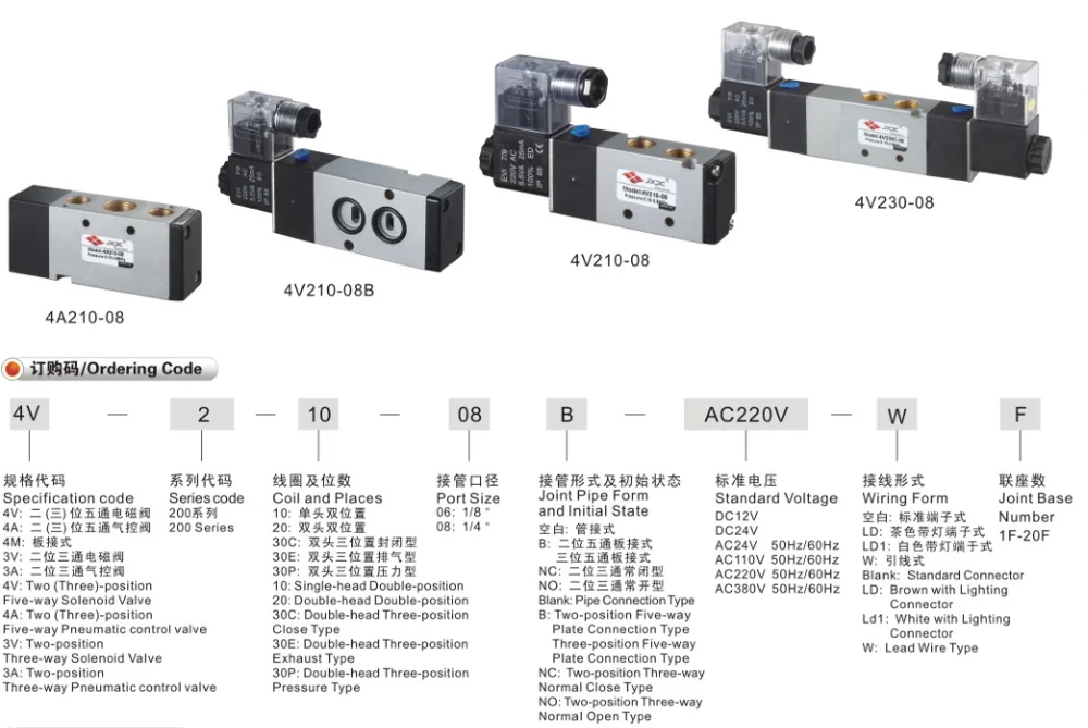
There are different types of solenoid valves, including normally open (NO) and normally closed (NC) valves. The wiring diagram may vary depending on the type of valve and its intended application. Additionally, solenoid valves can be operated using different voltages, such as 12V, 24V, or 120V. Therefore, it is crucial to refer to the specific wiring diagram provided by the manufacturer for the correct installation and operation of the solenoid valve.
In conclusion, having a clear understanding of the solenoid valve wiring diagram is vital for efficient installation and troubleshooting. It ensures that the valve is connected correctly to the power supply and allows for proper control of the flow of liquid or gas. Always refer to the manufacturer’s instructions and consult a professional if needed to ensure the safe and reliable operation of solenoid valves.
Solenoid Valve Wiring Diagram
A solenoid valve is an electromechanical device that controls the flow of fluid through a pipe or tubing system. It is commonly used in various industrial applications where precise control of fluid flow is required. Understanding the wiring diagram of a solenoid valve is essential for proper installation and troubleshooting.
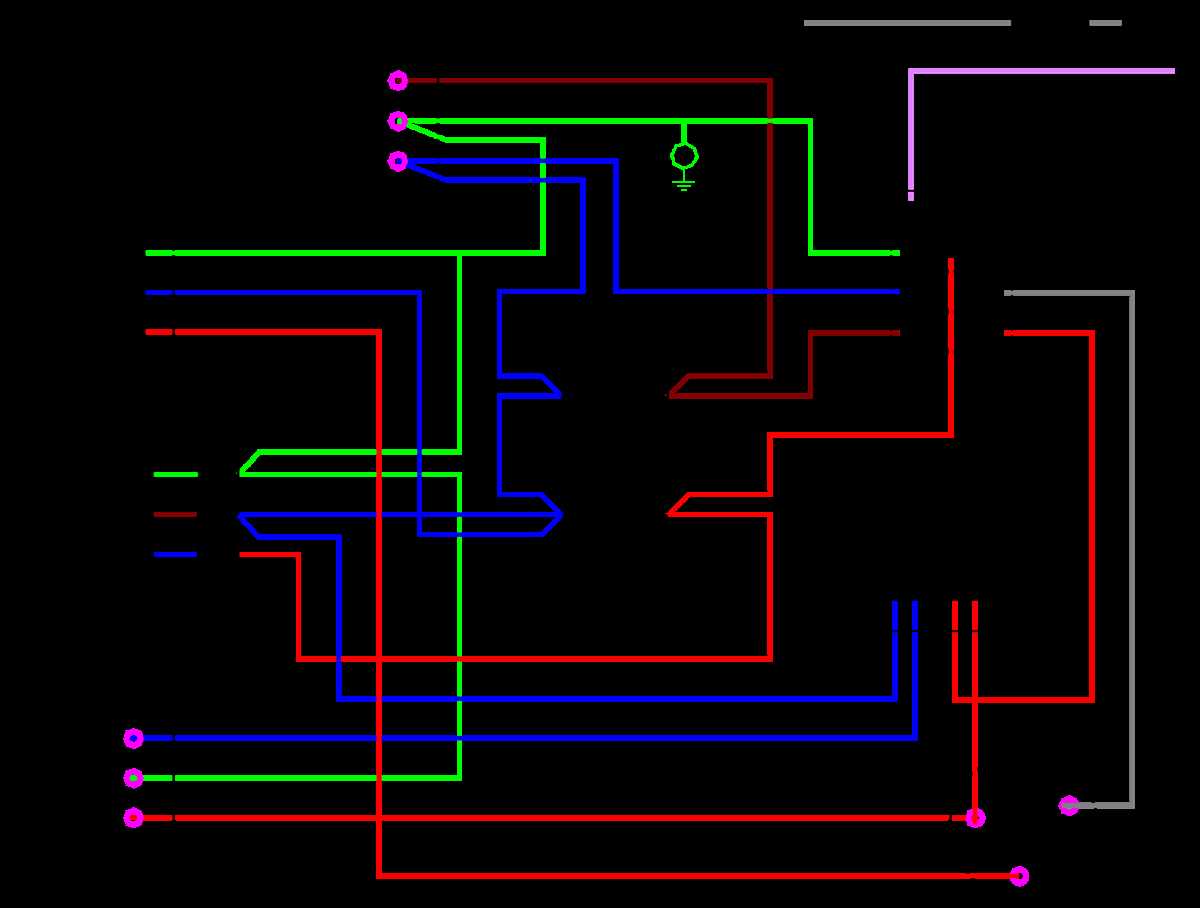
The wiring diagram of a solenoid valve typically consists of a power source, a solenoid coil, and a control device. The power source supplies the electrical energy needed to activate the solenoid coil. The solenoid coil is an electromagnet that generates a magnetic field when energized. This magnetic field pulls a plunger or piston within the solenoid valve, allowing or blocking the flow of fluid. The control device, such as a switch or relay, is used to control the activation and deactivation of the solenoid valve.
When wiring a solenoid valve, it is important to follow the manufacturer’s instructions and consult the wiring diagram provided with the valve. The diagram will typically indicate the terminals or wires that need to be connected to the power source, the control device, and the solenoid coil. It may also include information on any additional components, such as diodes or resistors, that are required for proper operation.
It is important to ensure that the correct voltage and current rating is provided to the solenoid valve, as exceeding these specifications can damage the valve or render it ineffective. Additionally, proper grounding of the valve and electrical connections is necessary to prevent electrical shocks or malfunctions.
Overall, understanding the wiring diagram of a solenoid valve is crucial for safe and effective operation. It allows for proper installation, troubleshooting, and maintenance of the valve, ensuring smooth fluid flow control in industrial applications.
What is a Solenoid Valve?
A solenoid valve is an electromechanical device that is used to control the flow of a liquid or gas. It is typically made up of a coil of wire, called a solenoid, and a valve body. The solenoid is an electrical component that generates a magnetic field when an electric current is passed through it. This magnetic field then attracts or repels a movable core, known as the plunger, which is connected to a valve mechanism.
When the solenoid is not energized, the plunger is in its resting position, which blocks the flow of fluid through the valve. However, when an electric current is applied to the solenoid, the magnetic field pulls the plunger towards it, opening the valve and allowing the fluid to flow. The flow can be controlled by adjusting the strength of the magnetic field or by using a spring mechanism to regulate the movement of the plunger.
The solenoid valve is commonly used in a variety of applications, including industrial processes, heating and cooling systems, irrigation systems, and automotive systems. It is often used to automate the flow of fluids, allowing for precise control and efficient operation. Additionally, solenoid valves are often preferred in situations where quick response times and tight shut-off capabilities are required.
Overall, the solenoid valve plays a crucial role in many industries and applications, providing a reliable and efficient means of controlling the flow of fluids.
The Importance of Wiring a Solenoid Valve Correctly
Proper wiring of a solenoid valve is crucial for its correct functioning and reliable operation in industrial applications. A solenoid valve is an electromechanical device that uses an electric current to control the flow of liquid or gas through a valve. It consists of a coil, a core, and a valve body. When an electrical current is applied to the coil, it creates a magnetic field that moves the core, opening or closing the valve.
When wiring a solenoid valve, it is essential to follow the manufacturer’s instructions and use the right wiring diagram. This ensures that the electrical connections are made correctly and that the valve operates safely. Incorrect wiring can lead to various issues, including valve malfunction, damage to other equipment, and potential safety hazards.
Here are some key points to consider when wiring a solenoid valve:
- Use the correct wire gauge: The wire gauge should be appropriate for the current carrying capacity of the solenoid valve. Using a wire with inadequate gauge can cause overheating and damage to the valve.
- Ensure proper insulation: The wires should be properly insulated to prevent short circuits and electrical shocks.
- Secure connections: The connections between the wires and the valve terminals should be tight and secure to avoid loose or intermittent connections.
- Observe polarity: Some solenoid valves have specific polarity requirements. It is important to connect the positive and negative terminals correctly to ensure proper operation.
- Protection against overvoltage: Adequate measures should be taken to protect the solenoid valve against overvoltage, such as using surge protectors or voltage regulators.
By wiring a solenoid valve correctly, you can ensure its reliable performance and prevent potential issues that could lead to downtime and costly repairs. It is always recommended to consult the manufacturer’s guidelines and seek professional assistance if needed to ensure the correct wiring of the solenoid valve.
Understanding the Components of a Solenoid Valve
A solenoid valve is an electromechanical device that controls the flow of various liquids or gases. Understanding the components of a solenoid valve is crucial for proper installation and maintenance of the valve.
Solenoid: The solenoid is the main component of the valve, consisting of a coil wound around a bobbin. When an electrical current is applied to the solenoid, it creates a magnetic field that attracts the armature towards it. This movement of the armature controls the flow of the fluid through the valve.
Armature: The armature is a movable component within the solenoid valve. It is attached to a plunger that opens or closes the valve by blocking or allowing the flow of the fluid. The armature moves in response to the magnetic field created by the solenoid coil.
Spring: The spring is an essential component that provides the necessary force to return the armature to its original position when the electrical current is removed. The spring ensures that the valve closes properly and prevents any leakage of the fluid.
Valve Body: The valve body is the housing of the solenoid valve, which contains all the internal components. It is typically made of durable materials such as brass or stainless steel to withstand the pressure and temperature of the fluid being controlled.
Seals: The seals are crucial for ensuring a tight and leak-free connection between the valve body and the fluid lines. They are usually made of rubber or other flexible materials that can withstand the specific fluid and temperature requirements.
Inlet and Outlet Ports: The inlet and outlet ports are the openings in the valve body where the fluid enters and exits the valve. These ports are connected to the fluid lines and are designed to provide smooth and efficient flow of the liquid or gas.
Understanding the various components of a solenoid valve is essential for troubleshooting any issues that may arise and for performing regular maintenance. Proper installation and maintenance of a solenoid valve can ensure its optimal performance and longevity.
Step-by-Step Guide to Wiring a Solenoid Valve
Wiring a solenoid valve is a straightforward process that requires attention to detail and following the manufacturer’s instructions. Here is a step-by-step guide to help you with the process:
1. Gather the necessary tools and equipment
Before starting the wiring process, make sure you have all the necessary tools and equipment. This includes wire strippers, electrical tape, a screwdriver, and of course, the solenoid valve itself.
2. Identify the terminals
Take a close look at the solenoid valve and identify the terminals. There are usually two terminals, marked as “+” and “-“. These terminals are where you will connect the wires.
3. Prepare the wires
Use wire strippers to remove the insulation from the ends of the wires that you will be using. Make sure to strip just enough insulation to expose the bare wire, without damaging the actual wire inside.
4. Connect the wires to the terminals
Take the stripped ends of the wires and connect them to the appropriate terminals on the solenoid valve. The “+” wire should be connected to the positive terminal, and the “-” wire to the negative terminal. Make sure the connections are secure and tight.
5. Insulate the connections
Once the wires are connected, use electrical tape to insulate the connections. This will help prevent any accidental short circuits and ensure the wiring is safe and secure.
6. Test the wiring
Before placing the solenoid valve into operation, it’s important to test the wiring to ensure everything is working correctly. You can use a multimeter to check for continuity and make sure there are no loose connections.
By following these steps, you can properly wire a solenoid valve and ensure it functions smoothly in your desired system. Remember to always consult the manufacturer’s instructions for specific wiring requirements, as the process may vary depending on the valve model and brand.
Tips for Troubleshooting Solenoid Valve Wiring
When dealing with solenoid valve wiring, it is important to make sure that the wiring is correctly installed and connected. If there are any issues with the wiring, it can result in the solenoid valve not working properly or not working at all. Here are some tips to help troubleshoot solenoid valve wiring:
- Check the power source: Make sure that the solenoid valve is properly connected to a power source. Verify that the power source is providing the correct voltage and that it is working properly. If the power source is not supplying the correct voltage, it may need to be replaced.
- Inspect the wiring connections: Inspect the wiring connections to ensure that they are tight and secure. Loose or faulty connections can result in the solenoid valve not receiving the proper electrical signal. Tighten any loose connections or replace any faulty wiring.
- Test the solenoid valve: If the wiring connections appear to be correct, test the solenoid valve to determine if it is functioning properly. Disconnect the wiring from the solenoid valve and use a multimeter to test the resistance of the solenoid coil. If the resistance is not within the specified range, the solenoid valve may need to be replaced.
- Check for shorts or breaks in the wiring: Inspect the wiring for any signs of damage, such as shorts or breaks. These can disrupt the electrical signal and prevent the solenoid valve from operating correctly. Replace any damaged wiring as necessary.
- Consult the wiring diagram: If you are still having trouble with the solenoid valve wiring, consult the wiring diagram or the manufacturer’s instructions for guidance. The wiring diagram will provide a visual representation of how the solenoid valve should be wired, and can help identify any potential issues.
By following these troubleshooting tips, you can identify and resolve any issues with solenoid valve wiring, ensuring that the valve operates correctly and efficiently.
Q&A:
How can I troubleshoot solenoid valve wiring?
First, check if the solenoid valve is receiving power by using a multimeter to measure the voltage at the valve’s terminals. If there is no voltage, check the wiring connections for any loose or disconnected wires. Also, check if the power source is providing the correct voltage. If the solenoid valve is receiving power but not functioning, check the wiring for any short circuits or damaged wires. Additionally, ensure that the solenoid valve is properly grounded and that there are no issues with the control signal from the controller.
What could cause a solenoid valve to not function?
There are several possible causes for a solenoid valve to not function. One common cause is a lack of power reaching the valve due to wiring issues, such as loose, disconnected, or damaged wires. Another possible cause is a faulty solenoid coil, which may need to be replaced. Additionally, the valve may be clogged or stuck, preventing proper flow. It is also important to ensure that the control signal from the controller is functioning correctly and that the valve is properly grounded.
How can I test if a solenoid valve is functioning correctly?
To test if a solenoid valve is functioning correctly, you can use a multimeter to measure the resistance across the valve’s terminals. The resistance should be within the specified range for the valve. If the resistance is outside of the range, it may indicate a faulty solenoid coil that needs to be replaced. You can also manually apply power to the valve and observe if it opens or closes as intended. Additionally, checking for any leaks or obstructions in the valve can help ensure proper functioning.
Can a faulty solenoid valve wiring damage the valve itself?
While faulty solenoid valve wiring may not directly damage the valve, it can prevent the valve from functioning correctly and potentially lead to problems. For example, if the wiring does not provide enough power to the valve, it may not open or close fully, resulting in improper flow control. Additionally, if there are short circuits or damaged wires in the wiring, it could cause the valve to receive incorrect signals or cause damage to other components in the system. Therefore, it is important to ensure that the wiring is in good condition to prevent any potential issues.
What are some common wiring issues with solenoid valves?
Some common wiring issues with solenoid valves include loose or disconnected wires, damaged wires, short circuits, and improper grounding. Loose or disconnected wires can prevent power from reaching the valve, while damaged wires or short circuits can cause electrical issues. Improper grounding can also lead to problems with the valve’s functioning. It is important to thoroughly check the wiring connections and inspect the wires for any signs of damage or wear to ensure proper operation of the solenoid valve.