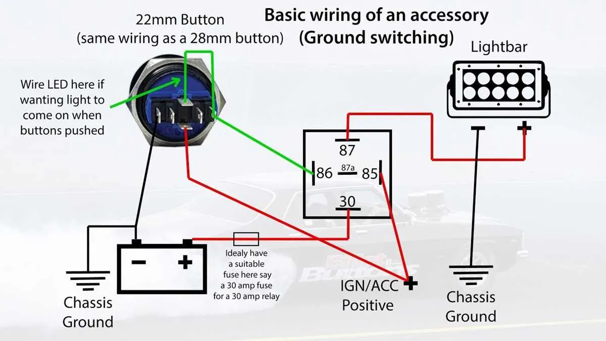
To ensure a reliable and safe installation of a basic electric control mechanism, begin by identifying the correct terminals for power and control. The power input usually connects to the primary terminal, while the secondary one serves as the output path when the mechanism is activated.
For a straightforward design, always ensure that the control lead is properly insulated to avoid any accidental short circuits. It is crucial that the circuit includes a protective fuse near the main power source to handle any sudden surges in current.
When working with multiple units in series or parallel, carefully map out the connections to avoid overloading any single path. A resistor may be necessary to balance the flow of electricity and prevent overheating of the components.
For best results, use high-quality copper wires with an appropriate gauge for the expected current. Double-check the wire connections, particularly where the control mechanism will engage, as these points are most susceptible to wear and tear over time.
Wiring a Momentary Control Device
For efficient connection of a momentary control device, identify the terminals: common, normally open (NO), and normally closed (NC). The common terminal is usually connected to the power source or ground, depending on the system’s design. The NO terminal should be linked to the device or circuit you want to activate, while the NC terminal is connected to the circuit that remains active when the control is not engaged.
For a basic configuration, connect the common terminal to the positive voltage, then wire the NO terminal to the component that will be powered. The NC terminal can be left unused in this scenario or linked to another circuit that should be interrupted when the device is triggered.
If the system requires a double-action (on/off), use a latching mechanism where the initial activation will close the circuit and the second action will open it. In this case, ensure both NO and NC terminals are properly engaged for both conditions, managing current flow effectively.
For more complex circuits, such as those requiring a relay or additional components, use the NO terminal to trigger the relay, which in turn powers the larger load. Proper insulation and secure connections are critical to avoid short circuits or overheating.
Always ensure that the wiring is correctly rated for the current and voltage levels to prevent any damage or hazards during operation. Proper grounding of the circuit can also help prevent electrical interference and ensure safe operation.
Pro Tip: If the device will be exposed to environmental factors like moisture or dust, consider using sealed versions with waterproof enclosures for increased reliability and safety.
How to Connect a Single-Pole Momentary Control for Basic Circuits

To set up a single-pole momentary control for basic electrical systems, start by ensuring the circuit is not powered. Connect one terminal of the control to the live wire from the power source. The other terminal should be linked to the load, which could be a light fixture or another device. The neutral wire from the power source must be connected directly to the load to complete the circuit when the contact is activated.
When the control is pressed, the circuit will close, allowing current to flow through the load. Upon release, the circuit will open, cutting off the current. Make sure to use insulated connectors to prevent accidental short circuits. Verify that the wire gauges are appropriate for the current rating of the load and the power source.
For safety, check that the control’s voltage rating matches the circuit’s power specifications. After making the connections, test the setup by pressing the control to ensure the load activates and deactivates correctly. Always double-check all connections before powering the system.
Wiring a Control Mechanism with Multiple Outputs for Control Systems

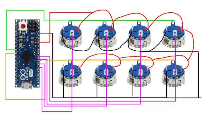
To control multiple outputs using a single activation device, connect the terminals of the control unit to the corresponding output circuits. The first step is to establish a common connection point, often referred to as the ground or neutral, which is shared by all output circuits.
For each output, ensure that one terminal of the mechanism connects to the common point, while the other is linked to the specific control system or device that needs to be activated. Use appropriately rated relays or transistors if higher current is required for controlling output devices like motors or lights.
In scenarios requiring sequential or simultaneous operation, you may opt for a mechanism with multiple contacts, which can be configured in a parallel or series arrangement based on the desired output behavior. Proper insulation and separation of circuits are crucial to prevent cross-interference.
In more complex setups, consider integrating a microcontroller or a digital controller to manage the logic of the outputs. This allows precise control over the timing and behavior of each output, offering advanced functionality like timed delays or conditional activation based on input parameters.
Make sure to test the entire setup thoroughly for proper functionality before deployment, ensuring that each output responds accurately to the activation of the control device. Additionally, always verify the voltage ratings to avoid damaging sensitive components.
Troubleshooting Common Connection Issues in Electrical Control Devices

When facing difficulties with control devices, the following steps can help diagnose and resolve common problems.
- No Response from Device: Check the integrity of the contacts. A loose connection or oxidized terminals can prevent proper functioning. Tighten and clean connections, ensuring they are free of corrosion.
- Intermittent Operation: If the device works intermittently, verify the stability of the wires. Insulate exposed areas and confirm there is no accidental grounding or short-circuiting along the conductors.
- Unresponsive Contact Points: If pressing the control does not result in a response, inspect the contact points for wear. Test continuity with a multimeter to ensure a proper flow of current when engaged.
- Excessive Resistance: Measure the resistance across the terminals. Excessive resistance can indicate damaged or degraded components within the device or the connection lines, affecting overall performance.
Ensure that any component in the circuit, including connectors and cables, is rated for the appropriate current and voltage to avoid overheating or malfunction. Regular maintenance can prevent these issues from recurring.
- Incorrect Polarity: For certain configurations, check if the positive and negative leads are connected correctly. Reversing polarity may cause malfunction or complete failure to operate.
- Failure to Reset: If the device does not reset as expected, check for an internal mechanical obstruction. Additionally, ensure that the reset mechanism is aligned and not physically blocked by debris or misalignment.
By thoroughly inspecting each element and adhering to these recommendations, most issues can be identified and resolved without the need for component replacement. Always consult the manufacturer’s specifications for the correct installation and maintenance procedures.