
When it comes to electrical systems, reading a wiring diagram is crucial. A wiring diagram is a visual representation of the electrical circuits and connections in a system. It is a detailed illustration that shows the components and how they are interconnected.
Wiring diagrams are used in a variety of industries, including automotive, residential, and industrial. They serve as a blueprint for electricians and technicians to understand the wiring layout and troubleshoot any issues that may arise.
Reading a wiring diagram can seem daunting at first, but with some basic knowledge and practice, anyone can learn to decipher these intricate diagrams. In this article, we will explore the key elements of a wiring diagram and provide tips on how to read and interpret them effectively.
Understanding Wiring Diagrams: An Essential Guide
When it comes to troubleshooting electrical systems or working on a project that involves wiring, understanding wiring diagrams is essential. Wiring diagrams provide a visual representation of the electrical connections and components in a system, helping you understand how everything is connected and where potential issues may lie.
One key aspect of reading a wiring diagram is understanding the symbols used. Different symbols represent various electrical components such as switches, relays, motors, and lights. It’s important to familiarize yourself with these symbols to be able to interpret the diagram correctly and identify the different components.
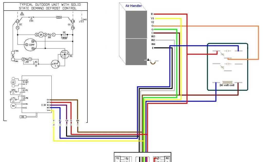
Another important factor to consider when reading a wiring diagram is the color coding of the wires. Each wire is typically assigned a specific color, which can indicate its purpose or function in the system. By understanding the color coding, you can easily follow the flow of current through the diagram and identify any potential wiring errors or malfunctions.
Additionally, wiring diagrams often include labels or numbers on the wires and components to further assist in identifying their purpose or connection point. These labels or numbers provide additional information and help ensure that the correct wires are connected in the right locations.
Overall, understanding wiring diagrams is crucial for any electrician or DIY enthusiast working with electrical systems. By taking the time to study and comprehend these diagrams, you can prevent costly mistakes, troubleshoot issues effectively, and ensure the safety and functionality of your electrical projects.
The Importance of Reading a Wiring Diagram
Reading a wiring diagram is of utmost importance for anyone involved in electrical work, whether it’s in the automotive industry, home repairs, or industrial settings. A wiring diagram is a visual representation of the electrical circuitry and connections within a system. It provides crucial information about the components, their location, and the way they are interconnected.
Understanding how to read a wiring diagram allows:
- Troubleshooting: When a problem occurs in an electrical system, a wiring diagram is an invaluable tool for identifying the source of the issue. By following the lines and labels on the diagram, an electrician or technician can pinpoint the exact component or connection that needs inspection or repair.
- Installation and Repair: Whether you’re installing a new device or repairing an existing one, a wiring diagram guides you through the process. It shows the correct placement and connection of wires, enabling you to avoid mistakes and ensure the safe and efficient operation of the system.
- Upgrades and Modifications: If you’re planning to upgrade or modify an electrical system, a wiring diagram helps you understand how the existing components are connected and how new components can be integrated. This knowledge is essential for making changes without causing harm to the system or compromising its functionality.
In conclusion, reading a wiring diagram is an essential skill for anyone working with electrical systems. It provides valuable insights into the circuitry, helping with troubleshooting, installation, repairs, and modifications. By being able to interpret and follow a wiring diagram accurately, individuals can work effectively and safely in various electrical applications.
Basic Components of a Wiring Diagram
A wiring diagram is a visual representation of an electrical circuit or system. It uses symbols and lines to show the connections between different components. Understanding the basic components of a wiring diagram is essential for anyone involved in electrical work or troubleshooting.
Here are some of the key components you will find in a typical wiring diagram:
Symbols:
In a wiring diagram, symbols are used to represent different electrical components and devices. These symbols make it easier to understand the circuit and identify the specific components involved. Common symbols include lines representing wires, circles or dots for connectors, squares for switches, and triangles for ground connections.
Lines and Connections:
The lines in a wiring diagram represent the actual electrical connections between components. Straight lines indicate wires, while specialized symbols represent specific types of connections, such as a splice or a jumper wire. Arrows may be used to show the direction of current flow.
Components and Devices:
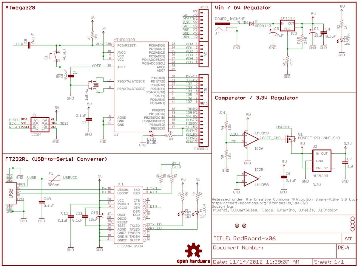
A wiring diagram will include a variety of components and devices depending on the specific circuit or system it represents. For example, you may see symbols for switches, relays, resistors, capacitors, motors, and more. Each component will be labeled with its corresponding symbol to indicate its presence in the circuit.
Labels and Descriptions:
To make the wiring diagram easier to understand, labels and descriptions are often included. These provide additional information about each component or device, such as its function, voltage rating, or location within the circuit. Labels and descriptions help to clarify the purpose and characteristics of each element in the diagram.
Power and Ground:
A wiring diagram will typically include symbols for power and ground connections. These symbols indicate where the electrical current enters and exits the circuit. Power connections are usually represented by arrows pointing towards a component, while ground connections are represented by a horizontal line with three downward-pointing arrows.
By understanding these basic components, you can interpret and navigate a wiring diagram effectively. Whether you are installing new electrical equipment or troubleshooting an issue, a thorough understanding of the wiring diagram will help you safely and efficiently work with electrical circuits and systems.
Interpreting Wiring Diagram Symbols
When reading a wiring diagram, it is important to understand the various symbols that are used to represent different electrical components and connections. These symbols provide a visual representation of how the different parts are connected and what function they perform in the circuit.
One of the most common symbols used in wiring diagrams is the straight line, which represents a wire or conductor. The line may have various arrows or breaks to indicate how the wire is connected or interrupted. It is essential to pay attention to the direction of the arrows as they indicate the flow of current in the circuit.
Other important symbols include circles or dots, which represent junction points or terminals where wires are connected. These symbols are often labeled with numbers or letters to identify specific connections. Additionally, there are various shapes and icons used to represent electrical components such as resistors, capacitors, switches, and motors. These symbols may have additional markings or annotations that provide further information about their specifications or functionality.
It is crucial to consult the key or legend provided with the wiring diagram to properly interpret the symbols used. The key will explain the meaning of each symbol and provide any necessary information for understanding the diagram. Taking the time to thoroughly understand the symbols and their meanings will enable you to accurately analyze and troubleshoot electrical circuits based on the wiring diagram.
Steps to Follow when Reading a Wiring Diagram
When working with electrical systems, it is essential to understand how to read a wiring diagram. A wiring diagram is a visual representation of the electrical connections and components found in a system. By following a few steps, you can effectively interpret a wiring diagram and troubleshoot any issues that may arise.
Step 1: Familiarize Yourself with the Symbols
The first step in reading a wiring diagram is to familiarize yourself with the symbols used. Wiring diagrams use various symbols to represent different electrical components such as resistors, capacitors, switches, and wires. It is crucial to understand these symbols to make sense of the diagram.
Step 2: Identify Power Sources and Ground Connections

Next, identify the power sources and ground connections in the wiring diagram. Power sources are typically represented by a + symbol, while ground connections are represented by a – symbol. Understanding these connections will help you determine where the electrical current is coming from and where it is being grounded.
Step 3: Follow the Flow of Electrical Current
Once you have identified the power sources and ground connections, you can follow the flow of electrical current through the diagram. Start at the power source and trace the path of the current through each component. This will help you understand how the different components are connected and how they interact with each other.
Step 4: Identify Switches and Connections
Pay attention to switches and connections in the wiring diagram. Switches control the flow of electrical current, and connections indicate how the various components are linked together. By understanding the switches and connections, you can determine which components are activated by the switches and how they are interconnected.
Step 5: Troubleshoot and Solve Issues

Finally, if you encounter any issues with the electrical system, you can use the wiring diagram to troubleshoot and solve the problem. By understanding how the components are connected and how the electrical current flows, you can identify the source of the issue and take appropriate measures to fix it.
Reading a wiring diagram is a crucial skill for anyone working with electrical systems. By following these steps and familiarizing yourself with the symbols, power sources, flow of current, switches, and connections, you can effectively interpret a wiring diagram and ensure the proper functioning of the electrical system.
Common Mistakes to Avoid when Reading a Wiring Diagram
Reading a wiring diagram can be challenging, especially for those who are not familiar with electrical systems. However, there are some common mistakes that people make when interpreting these diagrams. By being aware of these mistakes, you can avoid potential issues and ensure that you accurately understand the wiring diagram.
1. Not understanding the symbols
One of the most common mistakes is not understanding the symbols used in the wiring diagram. Electrical schematics use various symbols to represent different components and connections. It is important to familiarize yourself with these symbols before attempting to read the diagram. For example, a straight line represents a wire, while a zigzag line represents a resistor. Take the time to study the symbols to avoid confusion and misinterpretation.
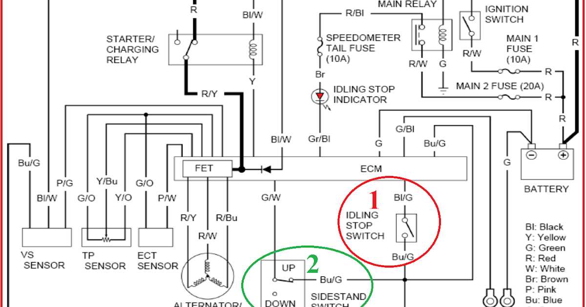
2. Ignoring color coding
Wiring diagrams often include color coding to indicate the different wires and their functions. Ignoring this color coding can lead to incorrect connections and potential electrical issues. Always pay close attention to the color coding in the diagram and ensure that you correctly identify and connect the wires according to their designated color.
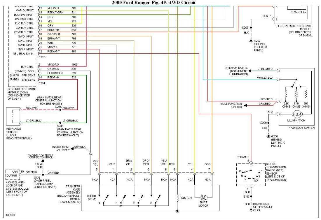
3. Overlooking wire paths
Another mistake to avoid is overlooking the paths of the wires in the diagram. The wiring diagram provides a visual representation of the electrical connections and routes of the wires. It is important to follow these paths accurately to ensure that the electrical system functions correctly. Failing to follow the wire paths can result in incorrect connections or even damage to the electrical components.
4. Not considering the sequence
Wiring diagrams often have a sequence or order in which the connections should be made. Ignoring or neglecting this sequence can lead to confusion and mistakes. It is crucial to carefully follow the sequence indicated in the diagram to ensure the proper functioning of the electrical system. Make sure to thoroughly analyze the diagram and understand the logical flow of connections before attempting to make any connections.
By avoiding these common mistakes, you can enhance your ability to read and interpret wiring diagrams accurately. Taking the time to understand the symbols, color coding, wire paths, and sequence will help you effectively navigate and understand the electrical connections in the diagram.
Advanced Techniques for Reading Complex Wiring Diagrams
Reading complex wiring diagrams can be challenging, but with the right techniques, it becomes much easier. Here are some advanced techniques that can help you navigate through complex wiring diagrams:
1. Break it down
Complex wiring diagrams often consist of multiple layers and components. One effective technique is to break down the diagram into smaller sections or subsystems. Focus on one section at a time and understand how the components are interconnected within that section. Once you have a clear understanding of each section, you can begin to piece them together to understand the entire diagram.
2. Identify common symbols
In complex wiring diagrams, there may be a multitude of symbols representing different components. It is important to familiarize yourself with the common symbols used in electrical diagrams, such as resistors, capacitors, switches, and connectors. This will help you quickly identify and understand the function of each component in the diagram.
3. Use color coding and annotations
Color coding and annotations can be extremely helpful when reading complex wiring diagrams. Different components, wires, or sections can be color-coded to make it easier to follow the connections. Additionally, adding annotations or notes to the diagram can help clarify any confusing or ambiguous information.
4. Utilize legends and reference materials
Large and complex wiring diagrams often come with accompanying legends or reference materials. These documents provide additional information about the symbols, colors, and abbreviations used in the diagram. Make sure to refer to these resources when encountering unfamiliar symbols or terms.
5. Practice and seek assistance
Reading complex wiring diagrams is a skill that improves with practice. The more you expose yourself to different types of diagrams, the better you will become at deciphering them. Additionally, don’t hesitate to seek assistance from experts or colleagues who are more experienced in reading wiring diagrams. They can provide valuable insights and guidance.
By applying these advanced techniques, you can confidently tackle even the most intricate wiring diagrams. Remember that practice and patience are key to becoming proficient in reading complex electrical diagrams.
Q&A:
How can I read complex wiring diagrams?
Reading complex wiring diagrams can be challenging, but there are several techniques that can help. It is important to start by understanding the symbols and labels used in the diagram. Additionally, breaking down the diagram into smaller sections and following the flow of the current can make it easier to interpret. Using color coding, numbering, and labeling can also simplify the process.
What are some common symbols used in wiring diagrams?
There are several common symbols used in wiring diagrams. These include lines to represent wires, squares or circles to represent junctions or connection points, arrows to indicate the direction of current flow, and various shapes and icons to represent electrical components such as resistors, switches, and capacitors.
What is the importance of understanding the flow of current in wiring diagrams?
Understanding the flow of current in wiring diagrams is crucial for correctly interpreting the diagram. By following the flow of current, you can determine how electrical components are connected and how they interact with one another. This understanding is essential for troubleshooting and repairing electrical systems.
How can color coding be helpful in reading complex wiring diagrams?
Color coding can be helpful in reading complex wiring diagrams because it allows for easier identification and differentiation of wires and components. By assigning specific colors to different types of wires or connections, it becomes easier to trace the path of a wire or identify its purpose within the electrical system.
What are some tips for understanding complex wiring diagrams?
Some tips for understanding complex wiring diagrams include studying the legend or key that explains the symbols and labels used, breaking down the diagram into smaller sections, seeking additional resources or explanations if needed, and practicing with simpler diagrams before moving on to more complex ones. It can also be helpful to consult experts or experienced professionals if you are having trouble interpreting a specific diagram.