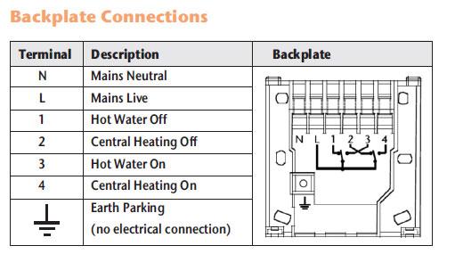
SALUS RT Electronic room thermostat for radiant a SALUS room thermostat.
In selecting the accordance with the wiring diagram. Instal- lation must also.
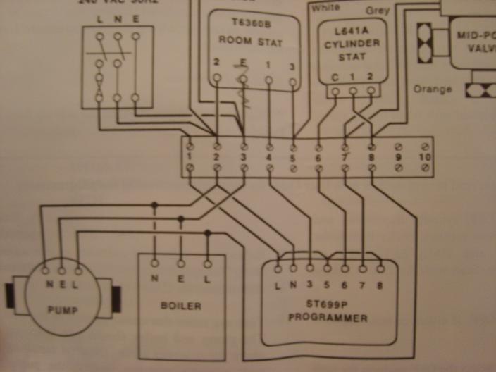
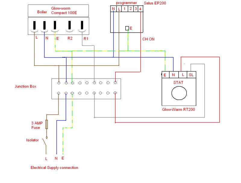
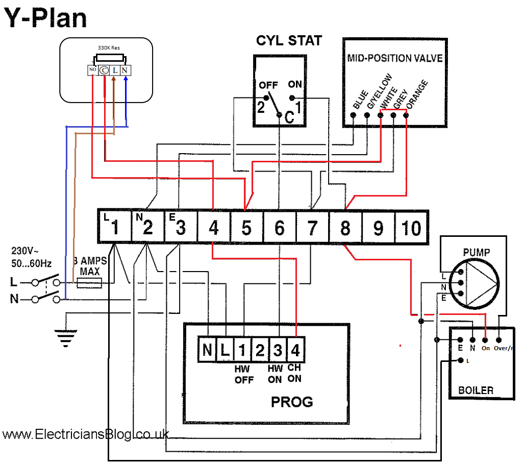
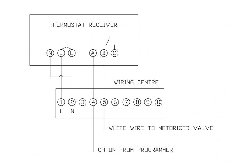
Wiring of Salus RTRF thermostat to Vokera Compact HE29 at the boiler, or airing cupboard using 5 core flex as shown in this diagram;. Manual Wiring diagram.
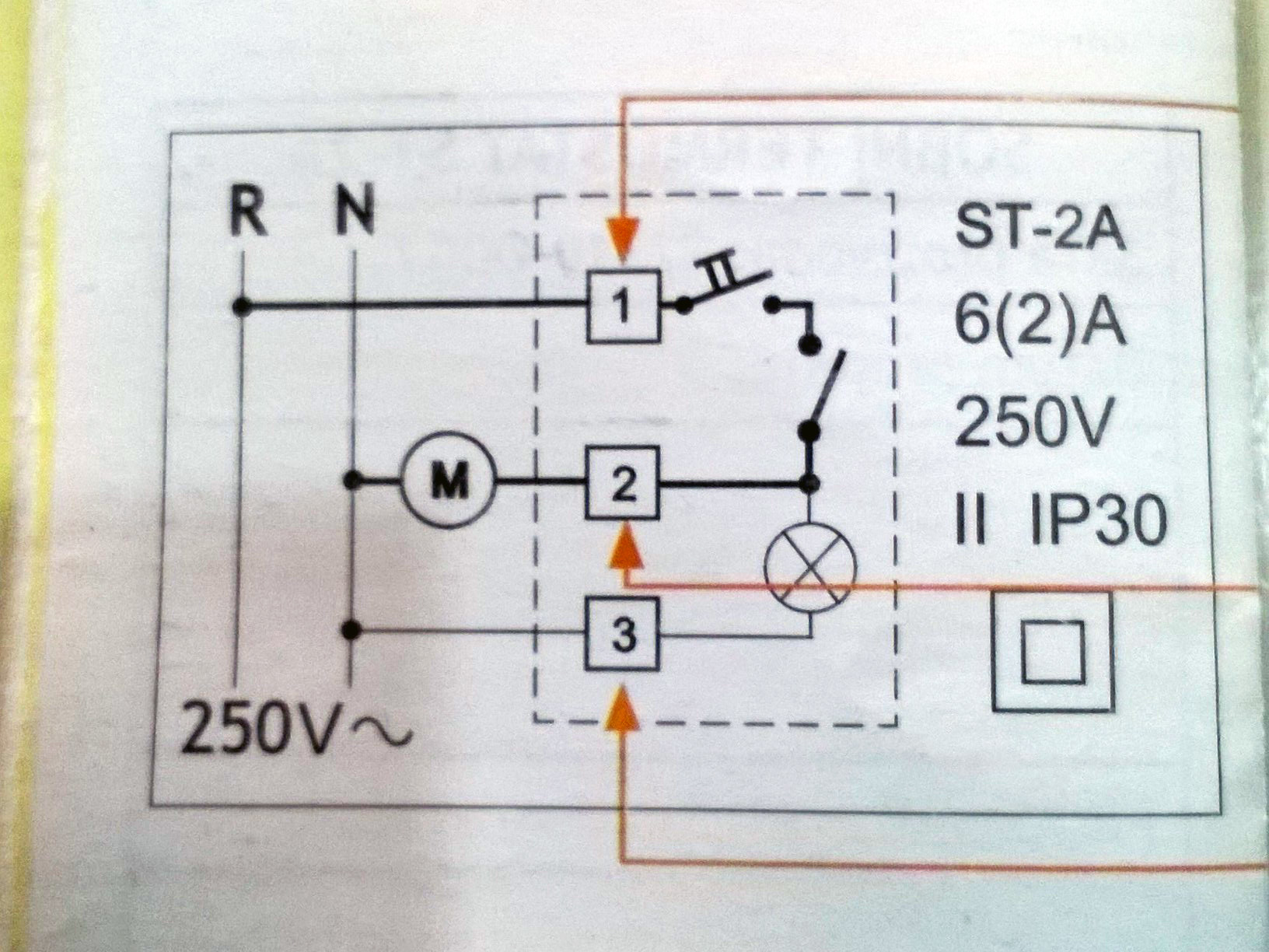
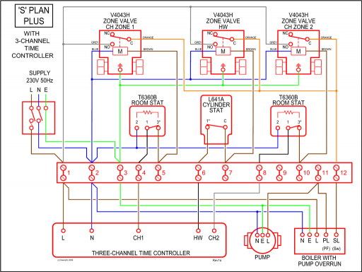
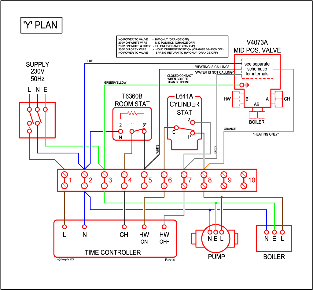
Logo Salus If you have any questions regarding SALUS’ processing of your personal information you are welcome to contact us. This is a diagram for wiring an RTRF to Y Plan. 3 Port Motorised Valve System (Y – Plan) with RF receiver.
L N. L N. Boiler.
Pump. E.
E. N E.
C. 1. 2.
E. Manual Wiring diagram Declaration of Conformity If you have any questions regarding SALUS’ processing of your personal information you are welcome to.Can be used in all heating applications with links for S & Y plan systems.
FEATURES. Easy to use; Simplifies wiring; Large terminals; Manufactured in flame-retardant plastic.
Download SALUS Controls manuals, spec sheets and quick guides for all our thermostats, programmers and underfloor heating control systems. We want to make it as easy as possible for you to get the best out of your SALUS products.
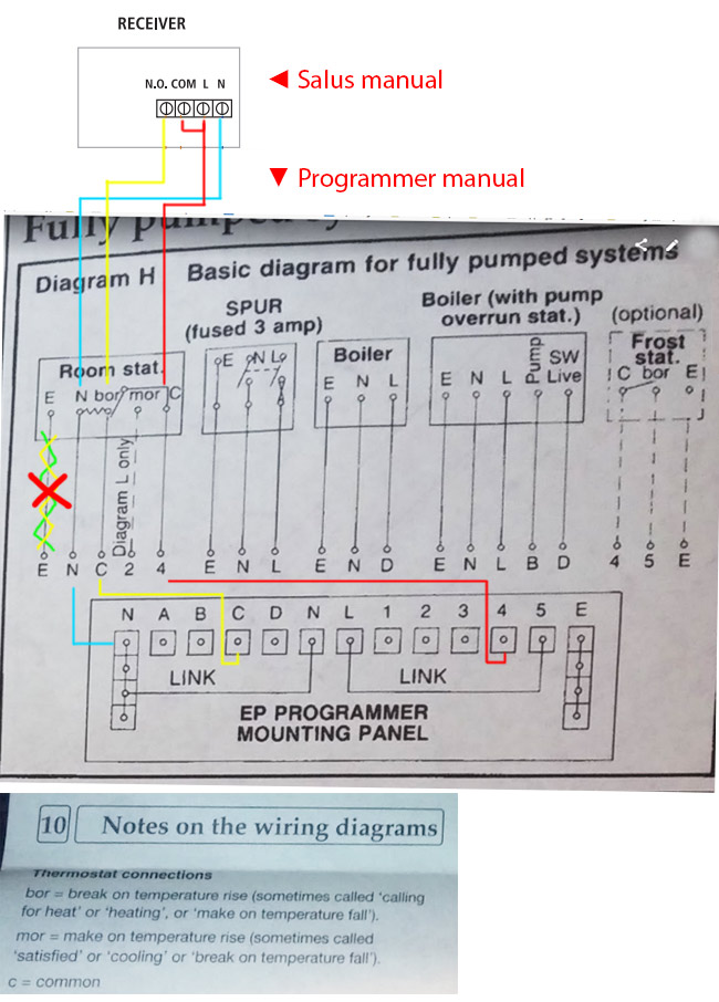
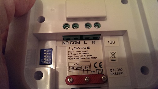
Nov 08, · I’m replacing a Danfoss RETP dial-type room thermostat with a Salus RT digital one in our upstairs ‘zone’. I thought it would be easy because I did something similar a few years ago downstairs replacing an old dial Honeywell with a digital DT Honeywell. WIRING DIAGRAM PRIOR TO INSTALLING PLEASE READ THE Wiring the Receiver for the RTRF INSTALLATION GUIDE FOR V APPLICATION 1) Remember to Isolate AC mains supply, note this INTRODUCTION must be V AC and fused at 13 amps max.
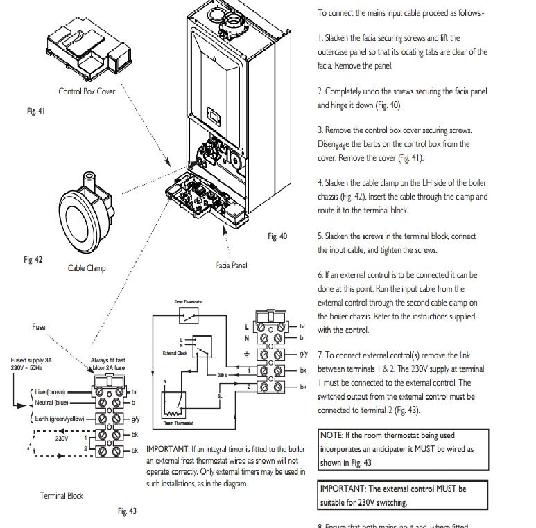
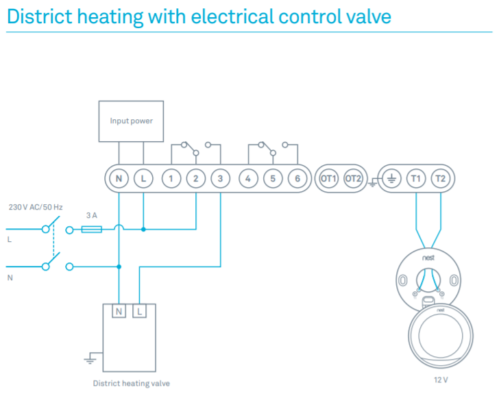
WIRING DIAGRAM WARNING: After removing the wall plate, if you 4. Connect the wires – see wiring diagram.
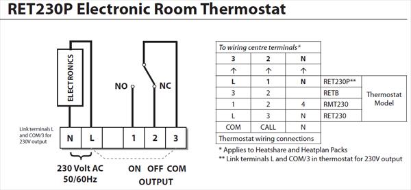
find that it is mounted on a junction box (e.g. a box 5. Push on the wires in the wall.
FOR V APPLICATION similar to one behind a light switch or electric 6. Page 7. WIRING DIAGRAM WIRING DIAGRAM s – see wiring diagram.Salus Wiring Centre – UK – Thermal Earth Ltd.SALUS RTRF INSTRUCTION MANUAL Pdf Download.
