
This manual contains notices you have to observe in order to ensure your personal Siemens products may only be used for the applications described in the. s.
SINAMICS. G Control Unit.
CUS. CUS DP.
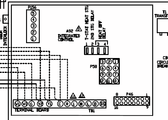
CUS DP-F. Software . Control wiring for a CUS Control Unit with default setting. B.
SINAMICS. G Control Units CUE.
Operating Instructions. 10/ This manual contains notices you have to observe in order to ensure your. This manual describes how you install the CUB-2 or CUE-2 Control Unit of the.
SINAMICS G inverter and commission it. What is the meaning of the.

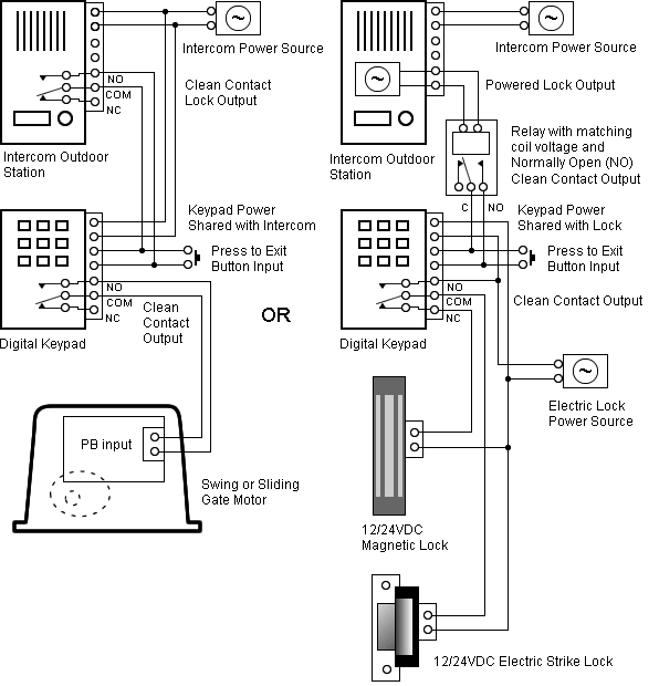
Siemens Sinamics G Manual Online: Wiring Diagrams. Overview Since the Sinamics g inverter with cup-2 control units ( pages). Control Unit.Wiring example for parallel connection of Motor Modules in vector control mode Commissioning Manual Commissioning Manual, (IH1), 01/, 6SLAFBP1.
SINAMICS G Inverter chassis units kW to kW ( hp to hp) SINAMICS G chassis units Siemens D · 3/3 3 Overview (continued) Modularity SINAMICS G is a modular converter system comprising a variety of functional units. The two main units are • the Control Unit (CU) and • the Power Module (PM). View and Download Siemens Sinamics G operating instructions manual online.
Radio Wall Transmitters Intelligent Operator Panel. Siemens Sinamics G Operating Instructions Manual.
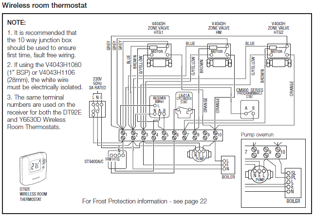
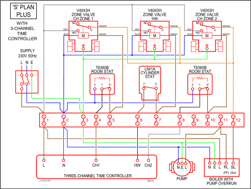
according to the relevant wiring diagram for the specific application wizard. All wiring of the Inverter, motor and any other devices used within the. s 04/ A5EB AA SINAMICS SINAMICS G CUP-2 Control Units List Manual Fundamental safety instructions 1 Parameters 2 Function diagrams 3 Faults and alarms 4 .
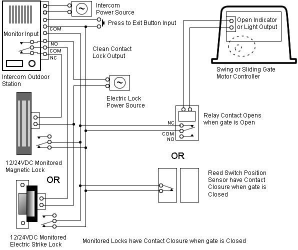
The EN safety functions of the SINAMICS G are fully integrated into the drive and include Safe Torque Off, Safe Stop 1, Safety Limited Speed and Safe Brake Control. As a result, production plants obtain greater levels of safety while requiring less overhead to integrate the drives into fail-safe, automation, and drive environments.Wiring Diagrams – Siemens Sinamics G Operating Instructions Manual [Page 43]SIEMENS SINAMICS G OPERATING INSTRUCTIONS MANUAL Pdf Download.
