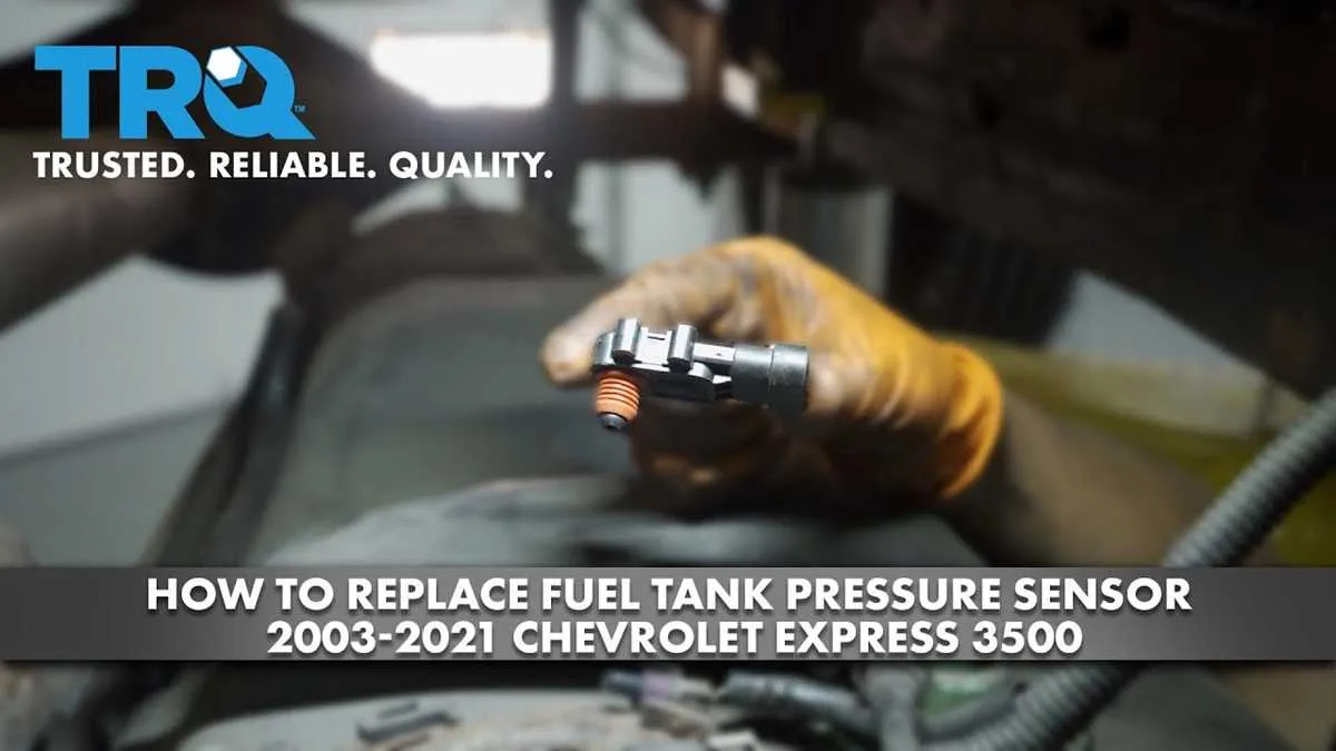
The device that monitors the pressure within the fuel containment system is typically located near the fuel cap or along the fuel line, depending on the vehicle make and model. If you’re troubleshooting or replacing this component, it’s important to focus on these common areas: the fuel rail, the line near the engine, or near the vapor recovery system.
In most vehicles, you’ll find this device connected directly to the fuel delivery system. For easier access, check the engine bay, specifically close to the fuel injector system or the purge valve assembly. If you’re unsure of the exact spot, referring to your vehicle’s service manual can save time and help avoid unnecessary disassembly.
Tip: Some advanced models include a diagnostic port for easier troubleshooting. Before starting any repairs, ensure that all fuel-related lines are properly sealed to prevent leaks during testing or replacements.
Fuel System Component Placement

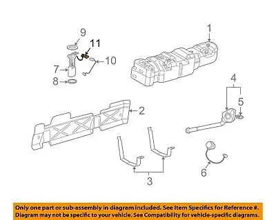
The component responsible for monitoring internal airspace in the containment vessel is typically mounted near the upper section of the fuel reservoir, closer to the cap. It is commonly placed at the junction where the tank’s air channel meets the vent system, which ensures precise measurement of vapor levels.
This part is crucial for detecting changes in the environment inside the containment structure, helping to maintain an accurate system reading. When locating this unit, ensure it is positioned away from direct heat sources to avoid temperature interference with measurements.
Accessing the assembly often requires removal of the top section of the fuel containment system or the access panel, depending on the vehicle’s design. The unit’s location is usually indicated in the vehicle’s service manual for ease of maintenance and replacement.
Ensure that wiring and connections are secure, as vibrations or wear could lead to inaccurate readings or failure. Regular checks should be performed to avoid issues related to air channel blockages or corrosion around the component area.
How to Identify the Component in Vehicle Schematics

To locate the specific component that monitors the internal atmosphere of the fuel container in your vehicle’s system, follow these steps:
- Look for a part connected to the evaporative emissions control system. It is typically near the fuel system’s venting components.
- Examine connections running from the canister purge valve to the control unit, as these often lead to the relevant sensor.
- Find the part attached to a small hose or wire harness leading to the main control system of the car’s emission system.
- It will typically be installed on or near the fuel system’s ventilation setup, which includes valves and check valves.
- Pay attention to components involved in pressure or vacuum regulation, as this part monitors the integrity of the fuel container’s pressure seal.
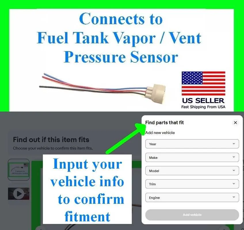
Check vehicle manuals or system guides for exact wiring color codes and pin assignments related to the component, as these will help identify it more clearly.
Common Locations of the Fuel Tank Pressure Sensor Across Different Car Models

The sensor responsible for monitoring the vapor system is typically found near the gas cap area, often integrated into the fuel vapor management system. In most vehicles, it is positioned close to the charcoal canister or along the lines connecting the fuel tank and vapor recovery system.
For many domestic cars, such as Ford and Chevrolet, the component is often located under the vehicle near the rear axle, attached to the canister purge valve. On Honda models, the sensor is usually placed near the tank’s vent line, tucked beneath the rear seat area, which facilitates easier access for maintenance. Toyota and Lexus commonly place this unit on the fuel tank assembly itself, or in some cases, near the pump module at the tank’s top end.
European manufacturers like BMW and Audi typically mount it within the tank or along the vapor return lines that run close to the exhaust system. These models often have a more centralized position under the rear wheel well, making the sensor accessible through the vehicle’s underbody panels.
In more compact cars, such as those from Kia or Hyundai, the sensor is often installed just inside the rear wheel arch, linked directly to the vapor vent system, allowing for streamlined performance within the smaller engine compartment layout.
Step-by-Step Guide to Accessing and Inspecting the Fuel System Monitoring Device
1. Lift the vehicle: Use a jack to raise the car, ensuring it is securely supported with stands for safety. The rear section should be slightly elevated for better access to the component.
2. Locate the access panel: Check beneath the vehicle, near the rear axle, where the device is typically positioned. If there is an access cover, remove it by unscrewing or unclipping, depending on the vehicle model.
3. Disconnect the battery: Before working with electrical components, disconnect the vehicle’s negative terminal to prevent any accidental short circuits or shocks during the inspection.
4. Examine the wiring: Trace the wires from the monitoring device, ensuring no signs of wear, corrosion, or loose connections. A thorough visual inspection of the cable insulation is crucial to identify any potential issues.
5. Unfasten the mounting bolts: Use the appropriate wrench to loosen the bolts securing the device. Keep these in a safe location to prevent losing them during reassembly.
6. Inspect the device: Once the monitoring device is exposed, check for any visible signs of damage, leakage, or wear. Ensure the device is securely fixed and the seal is intact. If there’s any visible rust or debris, clean the area gently before further inspection.
7. Test the functionality: Using a diagnostic tool, connect to the vehicle’s onboard system and verify if the device is transmitting the correct readings. A malfunctioning device might show inconsistent or no data on the system.
8. Reassemble and secure: After inspection, carefully reattach the device, tighten the bolts, and re-secure any wiring. Replace the access panel or cover, ensuring everything is back in its original position before lowering the vehicle.
9. Reconnect the battery: Finally, reconnect the negative terminal of the battery and start the vehicle to ensure everything operates as expected. Monitor the system for any warning lights or errors that may indicate further issues.