
Single phase alternators play a vital role in generating electrical power in various applications. They are commonly used in small-scale industries, residential homes, and commercial buildings. Understanding the connection diagram of a single phase alternator is essential for ensuring its proper operation and maintenance.
A single phase alternator consists of several components, including an alternator coil, rotor, stator, and various electrical connections. The connection diagram provides a visual representation of how these components are connected to each other and the external electrical circuits.
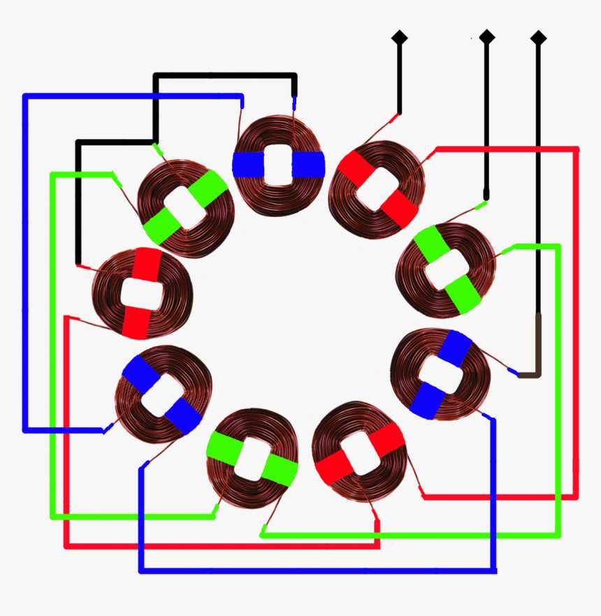
One of the key elements in the connection diagram is the alternator coil, which is responsible for generating the electrical current. It is typically made up of multiple windings or phases, depending on the specific design of the alternator. Each winding is connected to a different terminal, and together, they create a magnetic field within the alternator.
The rotor, on the other hand, is connected to a rotating shaft and is responsible for creating the magnetic field that interacts with the alternator coil. The stator, which surrounds the rotor, contains the output terminals and is connected to the load or the electrical circuits that will use the generated power.
Understanding the Single Phase Alternator Connection Diagram
A single phase alternator is a type of electrical generator that produces alternating current (AC) with a single phase. It is commonly used in residential, commercial, and industrial applications where a three-phase power supply is not available or required. To understand the connection diagram of a single phase alternator, it is important to know the components and their roles.
Components:
- Stator: The stator is the stationary part of the alternator that consists of a set of stationary coils arranged in a circular shape. These coils generate a magnetic field when an alternating current passes through them.
- Rotor: The rotor is the rotating part of the alternator that consists of a set of rotating coils or magnets. When the rotor spins, it induces a current in the stator coils.
- Excitation source: The excitation source is responsible for providing the initial current to start the generation process. It can be a battery or a separate electrical circuit.
Connection Diagram:
The connection diagram of a single phase alternator typically includes the following elements:
- Phase windings: The phase windings are the coils in the stator that are connected in a specific configuration to produce a single phase output. They are usually labeled A, B, and C.
- Field windings: The field windings are located on the rotor and are connected to the excitation source. They create a magnetic field that interacts with the stator windings to generate electricity.
- Output terminals: The output terminals of the alternator are where the generated electricity is delivered. They are typically labeled L1 and L2.
The connection diagram may also include other components depending on the specific design and application of the alternator, such as voltage regulators, capacitors, and protective devices.
Understanding the single phase alternator connection diagram is essential for proper installation and operation. It helps electricians and technicians to correctly connect the various components and ensure the reliable and efficient generation of electricity.
What is a Single Phase Alternator?
An alternator is an electrical device that converts mechanical energy into electrical energy. It is widely used in various industries and applications, including power generation, automotive, and marine sectors. A single phase alternator is a type of alternator that operates on a single phase AC power supply.
A single phase alternator consists of a rotating magnetic field and a stationary armature. The rotational motion of the magnetic field induces an alternating current (AC) in the armature coils. This AC output can be used to power electrical loads or battery charging.
In a single phase alternator connection diagram, there are typically two main parts: the stator and the rotor. The stator is the stationary part of the alternator that contains the armature coils. The rotor is the rotating part of the alternator that generates the magnetic field.
The connection diagram of a single phase alternator may vary depending on the specific design and application. However, the basic principles remain the same. The AC output from the armature coils is often rectified to produce a direct current (DC) for efficient power transmission and utilization.
In summary, a single phase alternator is an electrical device that converts mechanical energy into electrical energy by utilizing a rotating magnetic field and a stationary armature. It is a crucial component in various industries and applications, providing reliable power generation and electrical supply.
Components of a Single Phase Alternator
An alternator is an electrical device that converts mechanical energy into electrical energy. A single-phase alternator is specifically designed to produce a single-phase AC (alternating current) output. It consists of several key components that work together to generate electricity.
Stator:
The stator is the stationary part of the alternator and is made up of a core and a set of winding coils. The core provides a path for the magnetic flux, while the winding coils are responsible for generating the AC voltage. The stator coils are evenly spaced around the inner circumference of the stator core, and their arrangement determines the number of phases the alternator can produce.
Rotor:
The rotor is the rotating part of the alternator and is mounted on a shaft. It consists of a field winding that is excited by a DC (direct current) source. As the rotor rotates, the field winding creates a magnetic field that interacts with the stator coils, inducing voltages in them. This electromechanical interaction results in the generation of electricity.
Slip Rings:
Slip rings are conductive rings that are fixed on the rotor shaft. They provide a means of transferring the generated AC voltage from the rotor to an external load. The use of slip rings allows the alternator to produce a continuous output voltage, even though the rotor is rotating.
Brushes:
Brushes are stationary carbon contacts that press against the slip rings, allowing the transfer of electricity between the rotor and external load. The brushes also serve to maintain the electrical connection and provide a path for the excitation current to flow through the field winding.
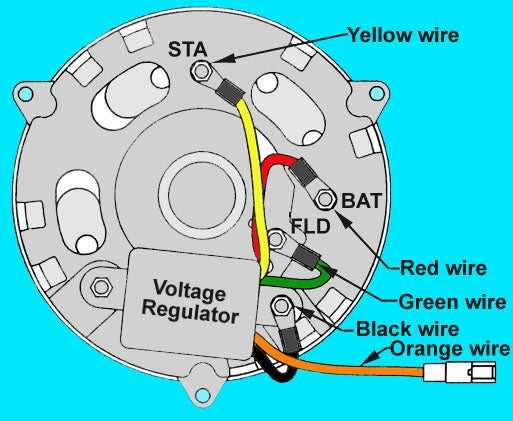
Voltage Regulator:
A voltage regulator is an essential component in a single-phase alternator. It regulates the output voltage to ensure that it stays within a specified range. This ensures that the voltage supplied to the load remains stable and protects sensitive electrical equipment from damage.
In summary, a single-phase alternator consists of a stator, rotor, slip rings, brushes, and a voltage regulator. These components work together to convert mechanical energy into electrical energy, providing a reliable source of power for various applications.
Single Phase Alternator Connection Diagram
In an electrical power system, alternators are commonly used to generate AC power. The connection diagram for a single phase alternator shows how the various components are connected to produce the desired output.
The main components of a single phase alternator are the stator, rotor, and voltage regulator. The stator is the stationary part of the alternator and contains the winding in which voltage is induced. The rotor is the rotating part of the alternator and generates a rotating magnetic field. The voltage regulator regulates the output voltage to maintain a steady supply of power.
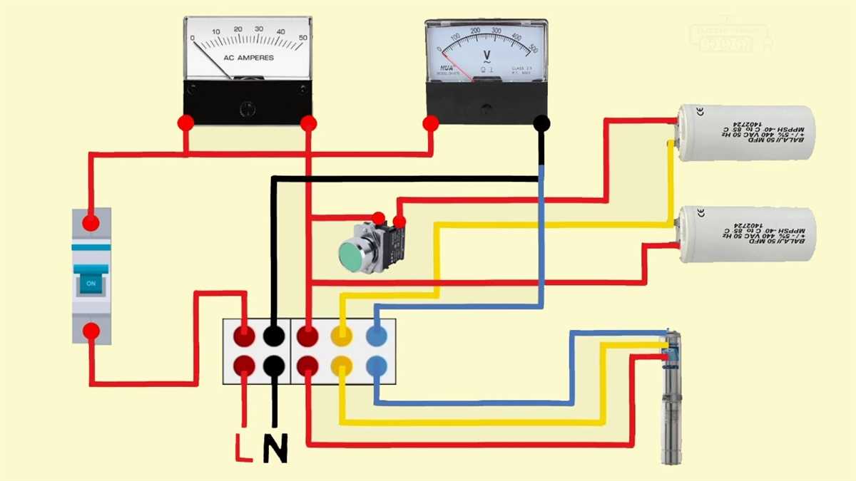
The connection diagram for a single phase alternator typically shows the terminals for connecting the load and the voltage regulator. The load terminals are used to connect the electrical load, such as lights or appliances, to the alternator. The voltage regulator terminals are used to connect the voltage regulator to the alternator to control the output voltage.
Some key features of the single phase alternator connection diagram include:
- The presence of a neutral terminal for connecting the neutral wire of the load.
- The presence of a grounding terminal for connecting the ground wire.
- The identification of each terminal with a label or symbol.
- The inclusion of any necessary switches or circuit breakers.
Overall, the single phase alternator connection diagram provides a visual representation of how the different components of the alternator are connected to produce the desired output. It is an important tool for understanding and troubleshooting the electrical system.
Benefits of Using a Single Phase Alternator Connection Diagram
Using a single phase alternator connection diagram can provide numerous benefits and advantages for electrical systems and applications. Some of the key benefits include:
- Improved understanding: By using a connection diagram, individuals can have a clearer and more comprehensive understanding of how the single phase alternator is wired and connected in a system. This can be especially helpful for technicians, engineers, and enthusiasts who need to troubleshoot, repair, or modify the electrical system.
- Easier installation: A connection diagram provides a step-by-step visual guide for the installation process. This can reduce errors and simplify the installation process, saving time and effort.
- Efficient maintenance: With a connection diagram, it becomes easier to locate and identify specific components and connections within the system. This can streamline the maintenance and servicing process, allowing technicians to quickly identify and fix any issues that may arise.
- Standardization: Connection diagrams often follow industry-standard symbols and conventions, making them easily understood by professionals across different sectors. This standardization facilitates effective communication and collaboration among technicians, engineers, and manufacturers.
- Enhanced safety: A connection diagram provides a visual representation of the electrical connections and can help identify potential safety hazards, such as incorrect wiring or improper grounding. By following the diagram, individuals can ensure that the electrical system is installed and operated safely.
In conclusion, using a single phase alternator connection diagram can greatly benefit electrical systems and applications by improving understanding, facilitating installation and maintenance, promoting standardization, and enhancing safety. Whether for troubleshooting, repairs, or new installations, a connection diagram is an invaluable tool for anyone working with single phase alternators.